CET1171 Lecture #10 - Component Identification #1

Materials:
Lecture Only
Objectives:
Be able to identify all major external devices and,
Discuss what each standard device does and,
Be able to identify standard cables and connectors,
Know all associated terminology including the meanings of the acronyms.
Competency:
The student will be able to inspect an unopened system and be able to identify all connectors, attached devices, and internal expansion cards that have external connectors.

Procedures

  1. Turn off the computer and disconnect the keyboard from the back of the system unit. The keyboard connector on the end of the keyboard cable is disconnected by pulling it straight outward from the socket. Note that this connector fits into a socket that is physically attached to the PC’s motherboard. Twisting this connector, bending it to the side, wiggling it, or shoving a unit back into the wall (or any other obstacle) can damage the keyboard socket on the motherboard. This effectively DESTROYS the motherboard and it would have to be replaced. At the rapid pace at which the PC is constantly evolving, a suitable replacement motherboard may not be available that can accommodate the original CPU forcing not only the replacement of one of the most expensive components in the PC – the motherboard, but also a replacement of another very expensive item – the CPU. Needless to say, care should be taken concerning the keyboard connector entirely because of what it is permanently soldered to: the motherboard.

  2. Note that the socket on the back of the system unit for the keyboard is referred to as a female socket and the associated male connector is on the end of the keyboard cable. This is true for both standard classic types of keyboard connectors.

  3. There are two standard classic types of keyboard connector. The larger of the two is referred to as the AT keyboard connector, or the DIN5 (5-pin) connector. This is a standard electronics external connector that had been around for decades: DIN - Deutsche Industrie Normung. The smaller of the two was introduced by IBM in their PS/2 line of microcomputers and is referred to as the PS/2 keyboard connector, or the mini-DIN6 (6-pin) keyboard connector. In modern systems a third type of connection of the keyboard to the system unit has become quite common: USB - Universal Serial Bus. But USB is a general purpose external expansion bus that can accommodate any kind of external peripheral, not just the keyboard. The AT and PS/2 keyboard connectors are for the most part designed for and dedicated to just keyboards. So these two are, properly speaking, keyboard connectors while USB is, properly speaking, a general purpose external expansion bus that can also support a keyboard.


    Standard original AT keyboard connector

  4. The original IBM PC motherboard featured only the DIN5 keyboard connector built into it. This continued in the IBM AT motherboard architecture. This meant that all other peripherals had to be added to the system with expansion cards including serial ports, parallel ports, the video controller, the floppy disk controller and the ATA controller for hard drives. Toward the end of the AT based systems more and more peripherals were being integrated directly into the motherboard.

  5. The ATX based motherboard includes many integrated peripherals as part of the standard and defines a standard rear panel region where these integrated peripherals and their associated connectors are located. The motherboard includes with it a real panel "punchout" plate that has all of the connector holes already made in it, the panel fits into all ATX based case chassis allowing the motherboard to mount to any ATX case and to carry any arrangement of integrated peripheral connectors.


    Standard ATX Rear Panel and Motherboard
    Integrated Peripheral Connectors
    Components Indicated
    1. Standard AC Power Cable and Connector
    2. 110V/220V AC Power Coneverter Switch
    3. PS/2 Style Mouse Connector
    4. PS/2 Style Keyboard Connector
    5. 2 USB Female "A" Connectors
    6. Parallel Port
    7. 2 Serial Ports
    8. Joystick/Game Controller Port
    9. 3 mini-phono jack connectors for integrated sound card
    10. Open expansion card slot for AGP Video Card
    11. First open PCI expansion slot
    Red arrow showing upper edge of ATX rear panel "punchout" plate

  6. Remove the mouse. There are two different classic types of mouse. The serial mouse and the PS/2 mouse. It should be noted that while many mice contain both sets of circuits and can auto-detect how they have been attached to the PC, this is not guaranteed especially on inexpensive generic mice. A serial mouse attaches with a female DB9 connector to the like sized male DB9 connector on the back of the system unit. These connectors are used by the standard serial port of the PC and so these are standard external peripheral expansion connections and not a dedicated mouse technology. Sketch the male serial port connector found on the back of the PC then sketch the female serial connector on a serial mouse cable. The PS/2 mouse connector is also a mini-DIN6 connector that is physically identical to the PS/2 keyboard connector, but internally the two ports are different and are not interchangeable. This is a dedicated connector for the mouse (or other pointing devices such a trackballs.) One of the most common keyboard/mouse problems on a PS/2 style PC is that the keyboard and mouse have been reversed by the user. The MPC specifications have standardized the colors of the connectors to be blue/purple for keyboard and green for the mouse, but motherboard manufacturers have also standardized the vertical arrangement of these connectors such that the keyboard connector is the bottom one (with respect to the plane of the motherboard surface) and the mouse connector is the top one. The third and now most common attachment of the pointing device is the USB connection and as already mentioned this is an industry standard expansion bus.


    Standard PS/2 type
    keyboard and mouse connectors

    Standard arrangement of the PS/2
    keyboard and mouse connectors

  7. Remove the monitor connector. For the past ten years the standard in video technology called VGA - Video Graphics Array has been gradually replaced by SVGA - Super Video Graphics Array. It is important to note that the same connector is used by both technologies: a non-standard high density 15-pin DB9 female connector is either built in to the motherboard if the video controller is built into it, or can be found on the video expansion card installed in an expansion slot of the motherboard. The monitor cable ends in the 15-pin DB9 male connector which is usually equipped with two screws to secure it to the system unit.


    Standard (S)VGA type connector

  8. It should also be noted that few video controllers or monitors actually use all 15 pins. Sometimes one or more of these pins will be missing which may make the connector look odd or even damaged. A VGA controller and monitor are capable of displaying 256 colors from a palette of 262,144 colors in 320X200 pixel resolution, or 16 colors from a 256 color palette in 640X480 pixel resolution. A pixel is a picture element or a single square dot on the screen. It represents the smallest unit of solid color out of which the system can construct images on screen. The more pixels wide-by-high the screen is divided into then the sharper the detail of the images. The more possible colors that the pixels can be rendered in will also make image color transitions common in real world images much smoother and life like as well. SVGA generally speaking means any resolution superior to VGA. It does have a definite resolution definition but this will be covered in detail in a later lesson.

  9. The original IBM PC featured two main types of "generic" external expansion/peripheral device ports: The serial port and the parallel port.

  10. On the back of the unit there is a female DB25 connector. This female DB25 connector on the system unit is the printer port or parallel port. Remember that a 25-pin DB25 female is a parallel or printer port and some systems have a male DB25 which is a serial port. Sketch the back of the unit emphasizing the number of pins and whether the connector is a male or female. Make a note the system’s power cable (completely standard for both system units and monitors). Observe the used and available expansion card slots.


    Standard classic serial port connectors (top)
    and Parallel port connector (bottom)

  11. The serial port features the male DB9 and DB25 connectors on the back of the system. The serial port itself is a UART - Universal Asynchronous Receiver/Transmitter chip. This peripheral device is integrated into the modern motherboards through the ISA bus and the UART is also attached to the male DB9 or DB25 on the rear panel of the system unit. The device can accept a byte of data from the CPU through its I/O Addresses on the ISA bus and the CPU can also send it commands concerning how to transmit and receive data (also received through the I/O Addresses). The UART will establish communications with the other UART on the cable through a very simple exchange of signals on the lines. Then the UART will transmit the byte one bit at a time down the transmit line. Here is the male DB9 connector found on the back of the PC:

  12. The UART has lines for receiving data (Pin 2) and transmitting data (Pin 3). This means that, depending on the UART, it can be a full duplex device that can transmit and receive simultaneously like a telephone. Half duplex, older UART's can only send or receive at any given time, like a radio. Simplex is one way communication like a coach yelling at the team through a bull horn. In that case communication can only go in one direction throughout the entire session. The UART has always been a half duplex or full duplex device featuring two way communication.

  13. The female DB25 port on the back of the PC is the parallel port. The parallel port was originally designed as a simplex communication port intended to transmit data to the external device one byte at a time in parallel across the eight data lines. However, high capacity external storage devices including backup tape drives influenced the development of a bidirectional port introduced in the IBM PS/2 line of personal computers. This port was further improved upon with the development of the EPP and the ECP ports. Two different high speed bidirectional ports that are now emulated in all modern motherboards that have a parallel port.

  14. The device establishes communication with the remote device with similar techniques used by the UART. More code is required in addition to the hardware to recognize and deal with the signals on the lines. The parallel port has evolved from the original PC's 8-bit unidirectional port to the latest high speed parallel ports:

    PortInputOutputResource/Notes
    SPP - Standard Parallel Port50KB/s150KB/sInput is 4 bit
    Bidirectional Port (SPP)150KB/s      150KB/s      Input modified to 8 bit
    EPP - Enhanced Parallel PortI/O=500KB/s - 2MB/sNew controller
    ECP - Enhanced Capabilities Port    I/O=500KB/s - 2MB/sUses DMA 3

  15. The standard parallel port connector has not changed despite the type of parallel port in the motherboard:

  16. The IEEE 1284 standard governs this port including the BIOS code support, through the pin outs through the operation of the EPP and ECP controllers and the cable quality.

  17. USB means Universal Serial Bus. USB is a nonprofit organization funded by many companies in the PC industry. The technology has been developed to interface with external devices at far greater speeds than the old UART's or parallel ports support and to be able to autoconfigure and/or load drivers using the Plug-n-Play standards of the PCI bus. To this end it has been an end user success.


    The original product box logo for USB devices


    The USB symbol found on devices, cables, connectors, etc.

  18. USB 1.1 was a slight modification of the original technology (a bug fix) and is considered the early standard. The main difference between USB 1.1 and 2.0 is the speed. USB 1.1 supports two different speeds or channels. The low speed channel has a serial data transfer rate of 1.5Mbps. The "Full Speed channel" has a data transfer rate of 12Mbps. Slower devices like keyboards and mice are built to use the "Lo channel". USB 2.0 includes full backwards compatibility plus a new "Hi Speed channel" at 480Mbps.


    The product box logo for USB 2.0 compliant devices.

  19. USB features an "A" connector and socket/receptacle. The PC's host controllers have the "A" receptacle that is flat and narrow. The external devices feature a "B" receptacle that is more square. A USB cable from host controller to external device then has an "A" connector on one end and a "B" connector on the other. This is done because the cable delivers +5VDC and ground to the peripheral devices whether they actually use it or not. If you plugged a straight through cable from one PC to another you would be connecting +5VDC to Ground in both directions, short circuiting both PCs which would result in rising columns of smoke from both of them! This is why the ends of the cables have different connectors, making sure that you will not inadvertantly try such a thing.

  20. USB includes aside from the +5VDC and ground lines in the cable, a positive data and a negative data line. Both are used simultaneously to transmit the serial bits to the other device. This means that USB can only work in half duplex mode, only one device can transmit at a time, but any device can transmit at any given moment to the host controller or vice versa. Devices can only communicate with the host controller, not with their peers and only one host controller can exist on a USB bus.

  21. Below are the various common USB xonnectors:


    Standard USB Connector ends of an external USB cable:
    "A" Male on the left and
    "B" Male on the right

    USB Connector ends of an internal USB Motherboard Expansion Slot Adapter:
    Two 4-pin IDC with ninth key pin (yellow connector) on the left and "A" Female on the right
    (the other connectors are 4-pin FireWire -small and black- and 6-pin FireWire)

    Standard USB Connector ends of an external USB cable:
    "A" Male on the left and
    5-pin "mini-B" Male on the right

    Standard USB Connector ends of an external USB cable:
    "A" Male on the right and
    4-pin "mini-B" Male on the left

    Standard USB Connector ends of a 5-in-1 cable adapter USB cable:
    Of particular interest is the "mini-A" in the center and
    the "A" Female on the right

  22. The USB host controller was invented after the release of PCI and is a true Plug-n-Play device made for the PCI bus. As such it can function using any system resources and the drivers will support this behavior. USB support was added to Microsoft operating systems starting with Windows 95 OSR2, though Windows 98 has better USB support. But even Windows 98 has problems recognizing the subsequent attachment of some USB devices that have already been attached and had their device drivers loaded. Windows ME and Windows 2000 finally resolved these issues and work well with USB devices.

  23. Sound cards are usually the only card with mini phone jacks to attach speakers and microphones to the PC. Some older cards used to have a volume control but all volume controls are software now. Older sound cards can also have a female DB15 connector for the game paddles or controllers. All modern sound cards no longer have these connectors, game joysticks and controllers are now USB devices. The mini-phono jack connectors are analog inputs and outputs for microphones and speakers. Some connectors carry pure digital signals to speakers that are designed to decode them. These are called "5.1" or "7.1" systems and so on. These are all surround sound systems that allow precise adjustment of the speakers levels, feeds, and positions within the room and can drive base woofer type speakers. Most analog systems add speakers in pairs with very little control over these levels and usually cannot independently drive a base woofer speaker. The colors of the sound card connectors have been standardized since the MPC '99 specification as:

    Pink Analog Microphone Input
    Lt. Blue Analog Line Level Input
    Lt. Green Analog Line Level Output for Main Speaker(s)
    Black Analog Line Level Output for Rear speakers (4-speaker systems)
    Silver Analog Line Level Output for Side Speakers (6-speaker systems)
    Orange Digital SPDIF* Output for Surround Sound Speakers (5.1 systems)
    *-SPDIF - Sony Phillips Digital Interface Format


    Typical audio connectors including the classic DB15

  24. The modem - Modulator/Demodulator is a device that converts serial digital data into sound waves and vice versa compatible for regular telephone system transmission. In modern times these are failrly well deprecated in favor of DSL - Digital Subscriber Line and cable "modem" based high speed Internet connectivity devices. Telephones, modems and DSL "modems" (Note: they do not convert the data into sound, the signal remains completely digital from the DSL node transceiver to the local telephone CO - Central Office, which is why the term is in quotes) all use a standard connector called the RJ-11 (Registered Jack) which has 4 contacts in it. The NIC - Network Interface Card, for local area networking uses a similar but wider connector called the RJ-45 which has 8 contacts in it. Cable modems attach directly to the cable television coaxial cable with a BNC type connector (There is much debate over what "BNC" stands for.) But the cable modem will most likely attach to the PC using networking cable that attaches to an internal NIC.

Review Questions

  1. On separate sheets of paper diagram and list all names for: the AT keyboard connector on the motherboard, the AT connector on the end of the keyboard cable, the Keyboard/Mouse connectors on the ATX motherboard, the serial port connectors on the system unit, the parallel connector on the system unit, the serial port connector on the end of a device cable, the parallel port connector on the end of a device cable, the (S)VGA connector on the back of the system unit, the (S)VGA connector on the end of the device cable, the end of the parallel cable that attaches to the printer

  2. What are the minimum external peripherals required to boot a PC and see if it is working?


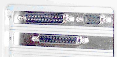
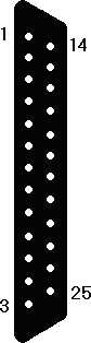
  3. Inspecting the back of a system unit, it has one male DB25 connector, one female DB25 connector, and two PS/2 connectors. Identify each one and explain why you cannot start up and use the PC as it is.


  4. A user has an incredibly cluttered office and is complaining that every once in a while the computer will not turn on and emits a rapid series of beeps. The user then has to turn it off and completely clean off her desk before the computer will work. The computer can't care about her clutter so what is the real problem?


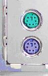
  5. A user complains that every time he moves his computer he has trouble because he accidentally reverses the keyboard and mouse connections. What kind are they and how do you know?


  6. A user complains that he just moved to a new office and now he cannot get onto the Internet. Assuming that he could before the move, the wall jack works, and the phone line appears securely attached to the top RJ-11 connector on the modem, what could the problem be?


  7. A user has moved his computer and now has no sound. All he did was move it and turn it on so the software can’t be wrong. He insists that he plugged the speaker cable into the unit, what is the problem?


  8. A user just bought a used computer and complains that his telephone cable connector is too small and won't plug into the modem's socket on the back of the unit. What is the problem?


  9. Many devices that used to be mounted on expansion cards in the early IBM AT and compatibles are often built in to the motherboard in modern systems. The only device that was built into the motherboard in the AT was the AT keyboard controller. List the peripherals that are commonly built into the motherboard in modern ATX systems.


  10. Many additional peripheral components can also be built into the ATX motherboard on modern systems. List these.


  11. List the keyboard connectors found on the system unit, to what component(s) are they directly attached? Which is a general purpose expansion bus not dedicated solely to keyboards (and mice)?


  12. List the mouse connectors found on the system unit, to what component(s) are they attached? Which are general purpose expansion attachments not dedicated solely to mice?


  13. What USB channel do keyboards and mice use? What is its speed?


  14. What is the fastest speed of a USB 1.1 controller? A USB 2.0 controller? How much faster is a USB 2.0 controller over a USB 1.1 controller?


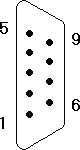
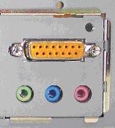
  15. A female 15-pin DB9 connector would be found where? What peripheral port is this? What external peripheral attaches to this? What type of connector does the external device cable have? What are two unusual features about this connector?


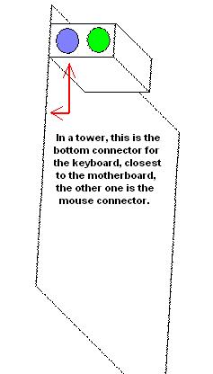
  16. Facing the back of a standing tower, is the PS/2 type keyboard connector most likely the left or right one? The mouse connector?


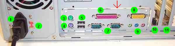
  17. Identify the sound connectors on the rear panel picture above from left to right.


  18. In the picture above of the ATX rear panel area, which connectors are actually on the motherboard standard rear panel? Which items are on the power supply?


  19. How much faster is an ECP port running at full constant speed possible over a USB 1.1 controller? How much faster than an ECP port is a USB 2.0 port? What is the fastest USB channel will a USB-to-Parallel port converter most likely use? Which USB channel is too fast for it to convert to?


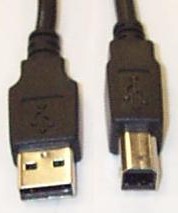
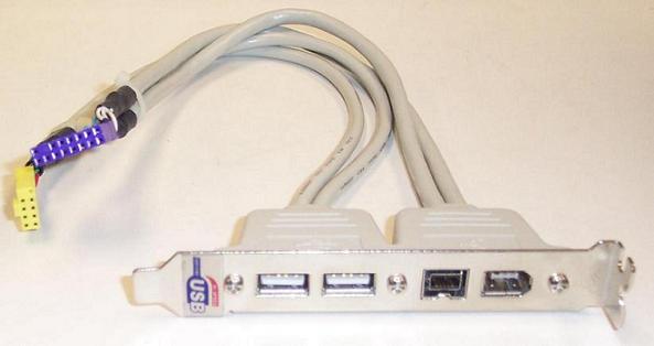
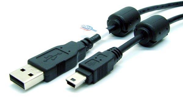
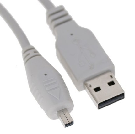
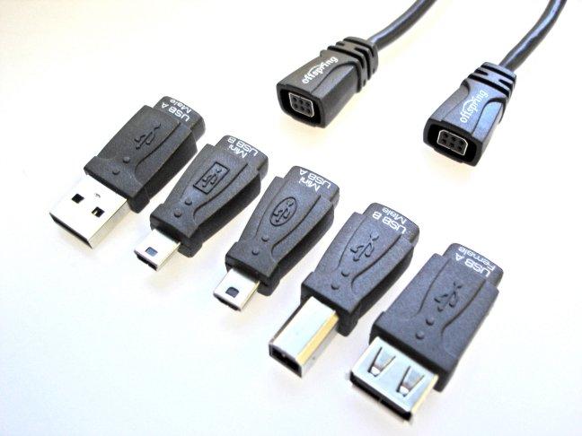
  20. Why are there no USB male "A" to male "A" connector cables? What are the typical connectors found on a standard USB peripheral cable? Name two other peripheral connectors commonly found on USB cables.


  21. USB peripherals can get their power from the host controller through the cable, what voltage is provided to them? Is USB serial or parallel communication? Is USB half duplex, duplex, or simplex communication? How many devices can a USB peripheral communicate with? How many USB hosts are allowed on one USB bus?


  22. You encounter a sound card that has four mini-phono jacks on it: pink, lt. blue, lt. green and black. This is most likely an analog or digital surround sound controller? This more than likely supports how many speakers?


  23. You encounter a sound card that has three mini-phono jacks on it: pink, lt. blue, and an orange connector. This is most likely an analog or digital surround sound controller? This more than likely supports a minimum of how many speakers?


  24. Since both sound cards mentioned above do not include a female DB15, what two things can be said regarding them?


Copyright©2000-2007 Brian Robinson ALL RIGHTS RESERVED