CET1171 Lecture #11 - Component Identification #2

Materials:
Lecture Only
Objectives:
The student will become familiar with,
The internal layout of an AT and ATX based system unit,
The layout of an AT motherboard,
The layout of an ATX motherboard,
The AT power supply,
The ATX power supply,
The standard motherboard interfaces.
Competency:
The student will become familiar with the internal layout of AT and ATX based microcomputers. The student will learn to identify AT and ATX power supplies and be able to identify the major connectors on AT and ATX architecture motherboards.

Procedures

  1. If the instructions are available on how to open the system unit’s case cover, then open the unit. Once open, the technician must immediately establish appropriate ESD safety procedures to ensure that none of the unit’s internal components will be damaged.

  2. It is imperative that the computer technician assert that all potential static electricity within himself and the system has been discharged to ground. Only then can the technician safely handle the system's components. This therefore requires the existence of a definite Earth ground to which the technician can attach and therefore discharge this static electrical potential.

  3. The student should immediately determine what type of power supply the computer has. Be sure not to touch anything at all. Even a casual brushing aside of cables can cause serious damage to the system while not exercising proper ESD procedures and if the system is an ATX, some circuits are active even when the system is "off" and if a cable happens to be loose, casually pushing it aside can detach it. Detaching an active circuit can completely destroy the components at both ends of the cable that gets detached while the circuit is on.

  4. First locate the power supply by observing the component into which the power cord attaches. Next; even though these usually have several groups of wires running from them out into the PC in various directions, most of these are groups of four: two black, one red and one yellow. These end in standard Molex power connectors for internal peripherals, usually drives of various types. However there should be a larger bundle of wires that goes from the power supply to the motherboard. Note the location and type of power connectors that run from the power supply to the motherboard.


    AT power supply-to-motherboard dual 6-pin edge connectors
    Connected "black to black" to the motherboard


    ATX power supply-to-motherboard single keyed 20-pin
    connector which cannot be accidentally reversed

  5. If there is a single block connector with two rows of ten or twelve (ATX 2.0) contacts each, it is an ATX connector. If there are two separate 6-pin straight edge connectors, these are AT connectors. Note that a motherboard with both sets of connectors is considered an ATX motherboard. But if that motherboard is attached to the power supply using the AT connectors then it is considered and is functioning as an AT system.

  6. The thick cable from the power supply to the physical throw switch is visible above the bundle of spare drive power cables and connectors and the two six pin connectors bring a bundle of twelve wires from the power supply to the motherboard near the center bottom of this image.

  7. The AT power supply is an older technology and has a thick cable that runs from the power supply case up to the front panel power switch making it easy to recognize. This is a real power switch that will arrest current flow within the power supply like a wall light switch will arrest current flow to the light and any exposed wires at the switch can yield a dangerous electrical shock or short circuit. The AT power switch is a push-on/push-off physical throw switch. This cable and real power switch are absent from the ATX power supply. The front panel power switch on ATX units is a momentary contact switch that leads to low voltage digital logic circuitry on the motherboard. When this circuitry detects the contact of the switch it sends the signal to the power supply to turn itself on or off.

  8. This means that this circuitry must remain active in the motherboard even when the system is "off" and there are other circuits that remain active monitoring for events that can be signals to turn the system on. One such event can come from the keyboard from a power on key. Another such event can come from either a modem receiving information intended for the computer to receive called WOR - Wake-on-Ring or a NIC - Network Interface Card can receive a packet intended for the system to receive called WOL - Wake-on-LAN. All of these technologies that are capable of turning on an ATX system are part of the ACPI - Advanced Configuration and Power Interface which in order to work must be implemented in the motherboard BIOS as well as the operating system device drivers for the devices.

  9. The ATX power supply was a planned technology whereas the AT (actually the baby-AT) accidentally evolved from the old original full sized AT. IBM experimented with the concept of making the power supply of the PC a peripheral component that could be controlled by software just like any other component in some of their post PS/2 486 based systems. These designs would be emulated by the industry and become the prototype for the ATX power supply design. The fact that the ATX power supply is a peripheral component under the control of the computer and its software makes this the main functional difference between the two types of power supplies.

  10. Additional specifications were added to the ATX specification including the positioning of the cooling fan in conjunction with the redesign of the ATX motherboard. Since the processor was going to be repositioned next to the power supply they rotated the fan within the power supply by 90° to face the processor and also had it blow across the processor meaning that it was drawing air in through the vents at the back of the power supply instead of blowing air out through them. The fan therefore serves a dual role of cooling the power supply itself as well as the processor. Pulling air into the case to escape through all of the cracks is referred to as a pressurizing cooling system as opposed to the AT in which the power supply fan blows air out of the vents meaning the air must seep in through all of the cracks and seams about the case. This is a depressurizing cooling system. Depressurization has the disadvantage that it draws dust in from every direction including floppy drive and optical CD-ROM drive doors which can then affect the heads and mechanics of the floppy drive and the laser optics and mechanics of the CD-ROM drive lowering their life expectancy.

  11. A disadvantage of the ATX pressurized cooling system is that almost all of the environmental air that enters the system enters through the rear vents of the power supply which means this device is going to collect most of the dust from the environment as well. ATX power supplies should be checked and vacuumed out regularly to avoid dust buildup on their high voltage circuitry. Interestingly enough this is considered an advantage of the ATX system since the rest of the PC including the drives remains fairly dust free, but it is only an advantage if the user knows that the power supply is going to clog with dust and makes plans to regularly clean it out.

  12. Another improvement of the ATX power supply was made in the power connector to the motherboard. This was changed from the old "P8"+"P9" six pin edge connectors which must be attached "black-to-black" (wires) and can accidentally be reversed shorting out and destroying the motherboard. Instead the ATX features a single keyed 20-pin connector that cannot be reversed by accident.

  13. The ATX power supply intended to provide the new +3.3VDC requirement of the new Intel Pentium processors and the front-side bus components. It provides this voltage, but each stepping in the Pentium models used different voltages with which a long-lived industry standard component could not keep up.

  14. Because of the fact that the processors and the front side bus motherboard chipset components have different voltage requirements every few months the ATX power supply specification certainly could not change at this rate and the reduced voltage Pentium MMX threatened to render the ATX specification obsolete before it was even ratified. The Socket 7 requirement to include a VRM - Voltage Regulation Module made it so that the ATX motherboard is still responsible for providing voltage regulators that generate the correct voltage for the processor and saved the ATX specification.

  15. The first and easiest test of any power supply is the functioning of the fan. If it has failed it can be replaced in many models but the best advice is to replace the whole power supply the logic being that since the circuits have been roasting without cooling for an unknown period of time then they have been subjected to possible latent damage. The life expectancy of the power supplies components has been compromised. Since the remaining life expectancy is an unknown variable, simply replace the device before it fails at the most inopportune moment. With the continual falling prices of the PC industry it is no longer advisable to replace a $5 power supply fan in a $10 power supply either. This is simply not cost effective considering the risk that the power supply is no longer reliable.

  16. Unstable power supplies are the single most difficult problem to diagnose. This is why it is so advisable to replace the power supply when its fan has failed. Digital Voltmeters however, are inexpensive and can at least give the stable average output reading on the wires. The industry states that a ±10% deviation of the output voltage on some output wires is acceptable. Although the author would personally toss any power supply with any line beyond ±5% deviation. The ATX power supply and digital voltmeters will be covered in depth in later lectures.

  17. The features and differences between the two power supply technologies:

    FeatureATATX
    Physical throw front panel on/off switchYesNo
    Logic signal front panel on/off switchNoYes
    Under the control of software/OSNoYes
    Dual 6-pin edge connectors to motherboardYesNo
    Single keyed 20-pin connector to motherboardNoYes
    Pressurizing cooling fanNoYes
    Depressurizing cooling fanYesNo
    Fan rotated 90° to move air over the CPUNoYes
    Generates ±5VDC and ±12VDCYesYes
    Generates +3.3VDCNoYes
    Deprecated technologyYesNo*
    Sends a POWER_GOOD signal to motherboardYesYes
    Automatically turns off under no loadYesYes

    * ATX 1.0 is quickly becoming deprecated in favor of ATX 2.0

  18. Standard power supplies are measured in Wattage of power that they can produce. Generally speaking a system with 1 HDD, 1 FDD, and 1 optical drive can usually be driven by a 200 to 250W power supply. However, the P4 processor alone can easily consume up to 70 or more Watts, not counting the rest of the motherboard and the drives. Many consumers are adding additional HDD's and optical drives like DVD-ROM drives and CD-R/RW burners to their systems. Each of these drives is a big power consuming device and such systems will need at least a 400W power supply or better.

  19. ATX 2.0 provides two additional sets of 4 power/ground lines to the motherboard. Four of these lines have been added to the ATX power supply-to-motherboard connector making it a single 24-pin keyed connector and the other four lines consisting of two +12VDC and two ground lines are provided by a separate single 4-pin keyed connector.


    The auxillary ATX power supply-to-motherboard 4-pin keyed connector

  20. The tools needed for exercising ESD safety while working on the PC were covered in a previous lesson and the steps for exercising proper anti-static procedures when working with an AT system are:

    1. Test the wall outlet - The first tool that should be used is therefore a wall outlet tester. They usually look like a standard three-prong appliance plug with no cord and a few LED's on them. Insert the outlet tester into the outlet where the system will be plugged into and be certain that the outlet is providing proper ground.
    2. Plug in the system to the tested outlet - This attaches the power supply to the outlet and therefore to ground. Internally the power supply connects the case to this source of ground as well. This is the only way that to assure that the system case is properly grounded.
    3. Be sure that the system is turned OFF - When the system is ON, then current is available throughout the system and a loose wire can touch the case and cause a short circuit which can trip a circuit breaker and throw out the power to the entire floor of the building. Not to mention cause damage to the computer's components.
    4. Remove the outer case housing - Follow proper procedures especially with name brand systems many of which have hidden releases and front facings made out of easily damaged plastic.
    5. Attach the anti-static wrist strap - At this point, put the strap on and attach the alligator clip of the anti-static wrist strap's cord to the bare metal edge of the system case chassis. The technician has attached to Earth ground through the case, through the power supply, through the known good tested wall outlet. Breaking this chain at any point completely negates its effectiveness such that one might as well take no anti-static measures at all.
    6. At this point, the technician can begin to work on the system.

  21. The anti-ESD protocol for the ATX system has to add some steps to the straighforward procedure used with the AT based system:

    1. (continued from above)Turn off the physical power switch of the ATX power supply. If it does not have one, then unplug the system. Either way, wait 10 seconds before proceding.
    2. Detach the ATX power supply-to-motherboard power cable(s). This will deactivate all of the ACPI compliant devices attached to and embedded within the motherboard. These are devices that continue to function even when the system is "off"
    3. If the system had to be physically unplugged, plug it back in. If it had to be turned off with a physical power switch on the power supply, that may remain in the off position. Plugging the system back into the wall outlet reestablishes contact with ground.
    4. At this point, the system and the technician are grounded, and all ACPI compliant devices have been deactivated and are now safe to work on.

  22. Identify the expansion bus slots. ISA (Industry Standard Architecture) slots are long and usually black. They have a small divider within them about 2/3 of the way back. This separates the original 8-bit side from the added 16-bit side. A 16-bit slot will accept either an 8-bit or a 16-bit expansion card. The 16-bit ISA slot also known as an AT Bus slot has 98-pins or contacts within the slot, 62-pins in the rear section and 36-pins behind the divider. Standard ISA cards are form factor dimensions are defined as: 4.2" (106.68mm) high, 13.13" (333.5mm) long and it is allowed a maximum width (occupying one slot) of 0.5" (12.7mm). Many ISA cards are physically much smaller than this. The ISA bus is much older and is 16-bits wide and runs at 8.33 Mhz. As an asynchronous bus taking between 2 to 10 clock cycles per data transfer across the bus will yield a maximum DTR of: 8.33Mhz x 2 Bytes/wave ÷ 2 clocks/transfer = 8.33MB/sec (maximum under ideal conditions which never happens.)

  23. The PCI (Peripheral Component Interconnect) slots are shorter and usually white. They are also a little farther from the back of the motherboard. The PCI bus is 32/64 bit wide technology and runs at 33 Mhz. The PC standard chose to use the 32-bit data bus width PCI slot and cards which have 124-pins or contacts. The form factor dimensions for a standard PCI card are the same as that for ISA cards but most PCI cards are physically much smaller. PCI is a synchronous bus, meaning that ideal conditions can be set up for a card to achieve 1 transfer per clock cycle so 32-bit PCI running at 33Mhz yields a maximum DTR of: 33Mhz x 4 Bytes/transfer = 133MB/sec (under ideal conditions such as "bus mastering")

  24. Identify any expansion cards attached to the expansion slots of the motherboard. Identify what type(s) of cards they are (i.e. sound card, video card, etc.) Note the locations of the cards. While ISA is not a slot sensitive technology, PCI definitely is. The bus controller and the driver are aware of which slot the card is installed in and if it is removed and then replaced into another slot, the bus controller will intepret this as the installation of a new device and pass this information on to the operating system which will then install a second set of drivers for the device. The problem is that it will not automatically remove the device from the slot where it once was and some drivers misbehave when they are installed for a device that does not exist.

  25. Most expansion cards have external connectors on their rear slot panel but there are notable exceptions, the first being an expansion ATA controller for EIDE hard drives. Since this is a purely internal technology (does not support external attachment of EIDE hard drives) then the rear slot panel of expansion card ATA controllers will be smooth and look very much like a vacant slot cover. Some SCSI - Small Computer System Interface, host controllers likewise have no external connectors even though the technology does support external device attachment to the bus, the particular controller may simply omit the connectors allowing for only internal SCSI devices.

  26. Identify the AGP (Accelerated Graphics Port) if the PC has one. The AGP was separated from the PCI bus by the video graphics manufacturers to allow it to run faster. AGP’s run at 66 Mhz though they have appeared as 2X, 4X and 8X these move 2, 4, or 8 bits per clock cycle and still run at 66MHz. The AGP port looks similar to the PCI slot but is typically brown and offset further from the back of the case. AGP is also a synchronous bus and is a 32-bit technology that can move 1, 2, 4, or even 8 bits per clock cycle. Depending on the port and the video controller this yields maximum DTR's of: 66Mhz x 4 Bytes/transfer = 266MB/sec, 2x moves 2 bits/wave or double the DTR = 533MB/sec, 4x moves 4 bits/wave or quadruple the DTR = 1066MB/sec and 8x moves 8 bits/wave for a DTR = 2133MB/sec. AGP 1x/2x slots support both signaling techniques (1 bit/wave or 2 bits/wave and run at 3.3VDC. These have a divider nearer to the rear of the system that accommodates a corresponding notch in the edge connector of the video card. AGP 4x/8x run at 1.5VDC and have a divider in the slot nearer to the front of the system and video cards have a corresponding notch in the edge connector. It should be noted that many AGP slots do NOT have the dividers even though they cannot properly detect 1.5V vs. 3.3V video cards or may not even be able to provide one of these voltages meaning at best it will yield insufficient voltage and the card will not work or at worst it will provide too much voltage and destroy the video card. It is always important to verify what type of AGP slot the system has before installing a new card to make sure that they are compatible. AGP slots have 132-pin edge contacts.


    ATX motherboard with PCI slots and AGP slot (rightmost near the center)

  27. Identify the PCI-Express slots if the PC has any. PCI-Express was developed under the name 3GIO - 3rd Generation Input/Output implying that ISA was the first generation universal expansion bus, PCI was the second and that PCI-Express will be the third. PCI-Express is however logically very similar to PCI. The only difference is the actual physical connections of the cards to the bus controller. Just like coaxial cable and connectors or Category 5 cable with RJ-45 connectors can either be used to carry Ethernet frames, i.e. the same logical communications, PCI cards and PCI-Express cards function very much the same, but physically connect to and transmit and receive their actual data over a different physical method. PCI cards transmit and receive their data in 32-bit parallel transmissions over a bus running at 33Mhz. PCI-Express cards transmit and receive their data over a single wire in 1-bit serial form at 2.5Ghz. Such an attachment is a small 36-pin low height slot called an "x1" slot, or a 1 lane slot. PCI-Express transmits data at 8-bits per 10-waves encoding method so the DTR is: 8-bits/10-wave x 2.5Ghz = 2Gb/sec. Divide this by 8-bits/Byte yields 250MB/sec. However, a PCI-Express card can use more than one channel at a time. An x2 card (though x2 slots are rare) would be capable of a 500MB/sec transfer rate. There are x4 (64-pin), x8 (98-pin) and x16 (164-pin) slots. There are also x32 slots but these and their expansion cards are not very common. PCI-Express (PCIe) 2.0 runs the lanes at twice the speed and they are backwards compatible. PCIe 3.0 Specification is expected to be complete in 2009 and specifies a clock speed of 8Ghz.


    ATX 2.0 motherboard
    Components Visible
    1. PCI-Express x1 slot
    2. 3 x PCI slots
    3. PCI-Express x16 slot
    4. 4 x SATA ports
    5. 1 x 40-pin Parallel ATA port

  28. An I/O controller card may feature serial port connectors and a parallel port connector (described above), it may also feature a floppy drive controller with a 34-pin jumper connector on it as well as a single or double 40-pin jumper block connector for IDE or EIDE devices. IDE stands for Integrated Drive Electronics and was the first comprehensive attempt by the storage device (hard drives in particular) industry to introduce a universal standard. It was a complete success but some manufacturers wanted greater power and flexibility in hard drive design while maintaining the universal standard. The result was EIDE or Enhanced Integrated Drive Electronics. EIDE improved upon IDE language, the set of commands which the ISA (and now PCI) attached controller would use to communicate with the controller built in to the hard drive itself, as well as allowed for a second complete channel on the bus using IRQ 15. This allows EIDE to handle up to 4 devices, 2 on each channel, while IDE only supports 2 devices on a single channel.


    40-pin Parallel ATA Connectors on the motherboard

  29. Modern systems including the standard ATX specification allow for many different peripheral devices that used to be available only as expansion cards to be built directly into the motherboard. The only peripheral that has always been integrated into the motherboard circuitry is the AT (or PS/2) keyboard controller and connector. Modern ATX motherboards also include typically:

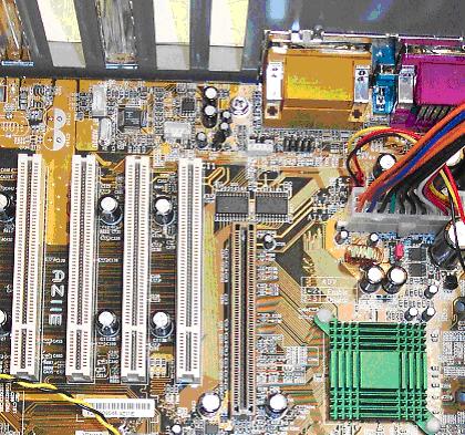
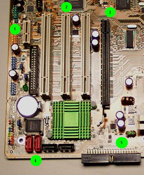
    Expansion bus integrated devices as well as expansion slots: ISA (deprecated), PCI (32-bit/33Mhz), AGP (1x/2x 3.3V as well as 4x/8x 1.5V), PCI-Express (x1 slots as well as x4, x8 slots and x16 for graphics)

    Two male DB9 connectors that are wired to serial port devices attached to an expansion bus in the motherboard. (deprecated)

    One female DB25 connector that is wired to a parallel port device in the motherboard. (deprecated)

    Two or more female USB connectors that are wired to a USB root hub device built into the motherboard.

    One male 34-pin block jumper connector, for attaching a standard floppy drive data ribbon cable, that is wired to a standard floppy disk drive controller integrated into the motherboard. (deprecated)

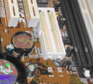
    Two male 40-pin block pin jumper connectors, for attaching standard or UDMA IDE data ribbon cables, that are wired to an IDE or EIDE (if there are two connectors) controller built into the motherboard. (deprecated - although one is still often found for optical drive attachment, hard drives now use SATA)

  30. Aside from the standard external expansion interfaces, a modern motherboard can often also include:

    One female 15-pin DB9 connector that is wired to a video controller in the motherboard.

    A female DB15 (deprecated) and one or more mini-phone jacks that are wired to the sound controller built into the motherboard.

    One or two RJ-11 (standard telephone) jacks that are wired to a modem built into the motherboard. (deprecated)

    One RJ-45 (standard networking interface) jack that is wired to a network interface controller built into the motherboard.

  31. Many internal and external peripherals get their power directly from the attachment interface to the motherboard. These devices are:

    RAM memory modules are always driven by the motherboard circuitry.

    Internal expansion cards including ISA, PCI, and AGP.

    Keyboard (AT, PS/2, and USB)

    Mouse (Serial, PS/2, and USB)

    Some smaller speakers are driven only by the output of the sound controller.

    Smaller USB devices including "key drives"

  32. Many internal and external peripheral devices do not derive power directly from their interface to the motherboard. These devices will always have an additional connection to the power supply within the system if internal, or to a power cable that plugs into an outlet for external devices. These typically include:

    Monitor

    Larger USB devices that have a separate power supply and cable that plugs into a wall outlet.

    Floppy disk drives

    Hard disk drives

    Optical drives (CD-ROM Readers, CD-ROM burners, DVD Readers, DVD burners)

    External serial devices that have a separate cable and plug into a wall outlet.

    External parallel port devices that have a separate cable and plug into a wall outlet including all printers that attach to the parallel port.

    Larger amplified speakers

  33. The two last major components of the PC attach directly to the motherboard: the CPU itself and the RAM modules. The common CPU that will be encountered is the Pentium generation of processors. However, there are many steppings of this generation of CPU’s and they vary widely in performance, architecture and physical packaging. The original Pentium or Pentium "I" was available in several SPGA socket designs culminating in the Socket 7. Socket 7 was modified by the industry leaders (other than Intel who invented the CPU and the socket) into the Super Socket 7. A modification that supported a 100Mhz front side bus speed. This is the speed of the communication at the pins of the socket to which the CPU is attached. 100Mhz meaning 100 million cycles or waves per second, indicates that the buses can move 100 million pieces of information across those bus pins per second.


    A typical AT motherboard layout

  34. It is important to remember that the actual AT motherboard is very large and rarely seen except in older true IBM AT’s, the "AT" motherboard being referred to here is actually the "baby-AT" a motherboard form factor that was a revision of the original IBM AT design intended to be much smaller and require a much smaller case. On the AT motherboard, the CPU socket is on the front left side of the motherboard when looking down into the case from the front. Long, full sized expansion cards cannot be inserted into some of the slots because of this positioning of the CPU. The RAM modules in the Baby-AT motherboard were typically located on the right side, when facing the system from the front, next to the power supply. This is generally the same location where the CPU is located on the ATX motherboard.

  35. On the ATX motherboard, the CPU socket (or slot) was moved from the old position of the AT to the other side. It now resides in the back to the far right, next to the power supply and directly in front of the rear panel connectors (including the keyboard connector). In the ATX motherboard the RAM module slots are on the front right hand side in front of the CPU.


    A typical ATX motherboard layout

  36. In order to actually start up a system to see if it works at all one needs a minimum of:

    1. Power supply - matching the motherboard type (AT, ATX, ATX 2.0)
    2. Motherboard
    3. CPU - that the motherboard will support
    4. RAM - minimum number, type and speed that the motherboard will support
    5. Keyboard - most POST routines in the BIOS will fail without a keyboard attached
    6. Video controller - can be built into the motherboard, otherwise it must be of an expansion bus type for which the motherboard has the appropriate slot
    7. Display - To be able to enter the BIOS and check and/or set configuration requirements for the system

Review Questions

  1. On separate sheets of paper diagram the general layout of the AT based system, the layout of the baby-AT motherboard of your system, the general layout of the ATX motherboard integrated connectors rear panel.

  2. Looking at the back of a PC you notice that all of the expansion slots have a smooth piece of metal in place. The computer therefore has no expansion cards. True or False? Explain your answer:


  3. You open an old computer and notice that the motherboard has a single male 40-pin connector block. This is most likely what kind of controller – be specific.


  4. A user claims to have bought an ATX case and power supply for his 486. He complains that it won’t automatically turn itself off from windows. Why?


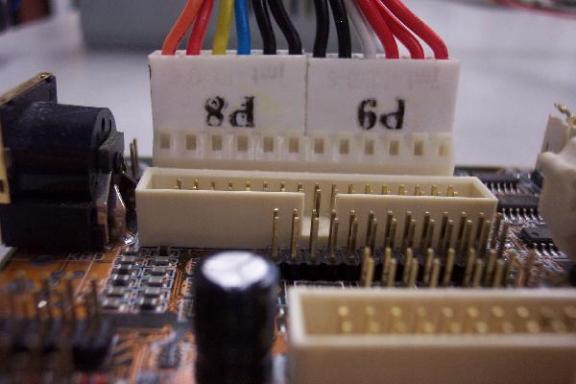
  5. A critical rule of thumb to remember for attaching the two AT power supply connectors to the motherboard is:


  6. Describe the proper ESD steps to take when working on an AT:


  7. What additional steps must be done on an ATX and why:


  8. Compare the ISA slots to the PCI slots (which is closer to the back of the motherboard, which has larger pins, what are the standard colors, which are to the far left and which are to the far right when viewing the motherboard from the front of the system)


  9. Describe the two ISA bus types. (Include the data bus width and clock speeds)


  10. Describe the standard PCI bus. (Include the data bus width and the clock speed)


  11. Define AGP and describe it. (Include the standard data bus width and speed)


  12. Once the case cover of the PC has been removed what is the first component that must be identified and why?


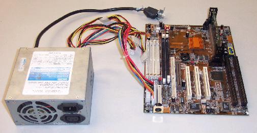
  13. What two methods of easily recognizing an AT versus an ATX power supply are discussed in this lecture?


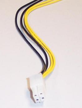
  14. What voltage does the ATX power supply provide directly to the system that the AT does not? What was this voltage originally intended for?


  15. Because each CPU has a different voltage requirement, what technology was introduced to provide the CPU with its voltage requirement that also "saved" the ATX specification?


  16. What feature of the ATX system introduces the extra steps in practicing proper anti-static procedures on these types of system?


  17. In observing the interior layout of the working machine, list all devices that get power through the motherboard (hint: they do not have separate connection to a power source).


  18. In observing the interior layout of the working machine, list all devices that do not get power through the motherboard (hint: they have a separate connection to a power source).


  19. List the two major components of the PC that are attached directly to the motherboard.


  20. List the type(s) of Pentium discussed in this lecture and their mounting systems.


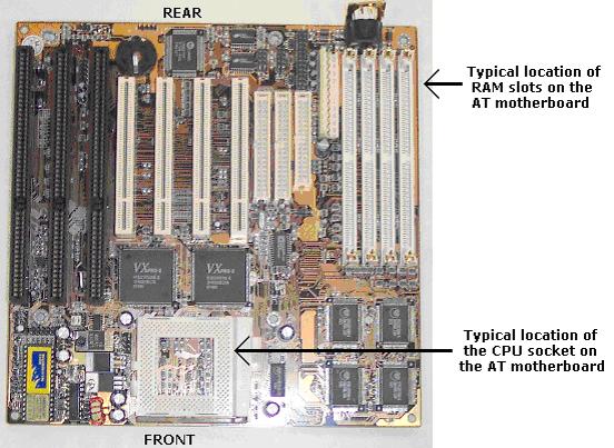
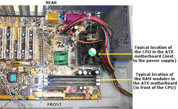
  21. Describe the location of the CPU in the AT and the ATX.


  22. Describe the location of the RAM modules in the AT and the ATX.


  23. Which external MPC compliant peripheral may derive power either from the connection to the system or directly from its own power source attachment to a standard wall outlet?


  24. Which type of external peripherals may derive power either from the connection to the controller or directly from its own power source attachment to a standard wall outlet?


  25. Which external peripherals never derive power from their own power source attachment to a standard wall outlet?


  26. Which external peripherals always derive power from their own power source attachment to a standard wall outlet?


  27. Which internal peripherals always derive power directly from their attachment to the motherboard?


  28. Which internal peripherals never derive power directly from their attachment to the motherboard and have a separate attachment to the power supply?


  29. Which internal peripherals remain active even when the system is turned off? These are found only on what type of motherboard?


  30. You have a motherboard with a single 40-pin ATA connector, what other type of connector should you look for to be able to distinguish it as a modern motherboard versus an ancient one?


  31. What are the numbers of pins in the ISA 8-bit slots, ISA 16-bit slots, PCI 32-bit slots, PCIe x1 slots, PCIe x16 slots, AGP slots?


  32. What are the DTR's of PCI 32-bit/33Mhz bus, AGP 1x, 2x, 4x, and 8x slots, PCIe x1, x4, x8 and x16 slots? SATA-1 has a DTR of 150MB/sec, what is the minimum standard expansion bus slot that supports this?


  33. A video card claims to have a DTR of 533MB/sec, what expansion bus slot does it most likely attach to?


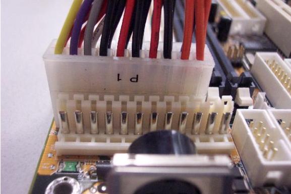
  34. Describe the AT power supply-to-motherboard power attachment. Describe the ATX 1.0 and ATX 2.0 power supply-to-motherboard attachments.


  35. List the differences between the AT and the ATX power supply. List the differences between the ATX 1.0 and the ATX 2.0 power supply.


  36. What is the ATX cooling method called? What is the main disadvantage of the ATX cooling method? Why is it a disadvantage?


  37. If PCI-Express 3.0 will use the same encoding method as the earlier versions, and the expected clock speed is 8GHz, then what will be the DTR of an x1 slot?


Copyright©2000-2008 Brian Robinson ALL RIGHTS RESERVED