CET1171 - The MPC '97 Specification
Materials: Working complete PCBlank DisketteStudent Diskette, "New Boot A Ver 2.0+" Working complete PCBlank DisketteStudent Diskette, "New Boot A Ver 2.0+"Objectives: The student should become familiar with: All major components and subsystems of the PC,Know all associated terminology including the meaning of acronyms.Competency: The student will begin to learn the complete parts list of which the modern end-user PC is built including a complete component inventory, the basic function of each component and connecting cables for the components. |
Procedures
-
In this lecture a complete overview of the all components necessary to build a working PC that will be to some extent MPC ’97 compliant will be examined. The MPC (Multimedia PC) ’97 Specification was initiated by many of the industry leaders including IBM and Microsoft in order to make sure that all PC’s intended for first time end-user buyers of PC’s would get a computer that had all functionality that a user would expect from a computer and would not have a computer missing some major feature and would then be forced to purchase parts and labor to make the computer capable of doing what the neighbor’s PC could do.
-
We will only use the MPC’97 specification as a parts list and will not delve into the detailed requirements of each component. The first component to consider is the case. There are two basic categories: desktop and tower. Within these two categories there are many subcategories, for now it is only important to be aware of the two and their differences. The desktop is the original case design of the PC. Later the desktop was turned up onto its left side if you are facing the front of it. So the left side of the desktop is the bottom of the tower, and the right side of the desktop is the top of the tower. All drive bays were then turned 90° so that drives would not be on their sides and this layout makes the tower case wider than the desktop is tall. Therefore towers are roomier inside which is one of the reasons they are popular with technicians. Towers also became popular with end-users because they do not occupy as much desk or floor space as the desktop. Often a monitor resting on top of the desktop sits too high and causes neck strain. By placing the monitor on the desktop itself next to the tower, the monitor is lower and easier to look at. Towers can also be placed on the floor under or next to a desk because they do not take up much floor space compared to desktops. The area the unit occupies is referred to as the system’s “footprint.”
-
Cases are designed with extremely precise screw hole locations that can accommodate power supplies and motherboards built to specification. In the computer industry an item may have certain specific dimensions such as a certain width, height, and depth, but it will also have the locations of the screw holes clearly and precisely defined so that the item will mount to the other items without the need for ever drilling holes or using adapter brackets. The item’s physical specifications ensure that it can interface with the rest of the system properly. The physical design of the item including its dimensions, screw hole layout and physical connector type and location are all collectively referred to as the item’s form factor.
-
Cases, both desktops and towers, came in two different form factors in 1997: AT and ATX. Since ATX was being phased in at the time and AT (actually Baby-AT) was being phased out, many cases were both AT and ATX. These form factors meant that if a case claimed to be “AT Form Factor” that all AT form factor power supplies and motherboards would mount to the case, all screw holes would line up with no problems. But since the case is not claiming ATX form factor, then an ATX power supply and/or motherboard may not necessarily mount to the case properly.
-
After the case, the next device to be considered is the power supply. From the above discussion it can be deduced that there are two different types of power supply: the AT and the ATX.
-
The AT has been deprecated by the industry. This means that no more AT type power supplies, motherboards and cases are in regular production, but the operating systems still support them. Once deprecated, future support for the device should not be expected, but it is still currently supported. A deprecated technology will be phased out and completely discontinued in the future. This means that future versions of Microsoft operating systems will at some point drop support for AT based systems. However, there still exist large numbers of AT power supply and motherboard based systems and all current operating systems do support these computers. Therefore the PC technician should be familiar with them. This technology was still manufactured as late as the Pentium II/III compatible motherboards. I have not seen any Pentium 4 based systems using AT power supplies.
-
The thick cable from the power supply to the physical throw switch is visible above the bundle of spare drive power cables and connectors and the two six pin connectors bring a bundle of twelve wires from the power supply to the motherboard near the center bottom of this image.
-
The AT power supply is an older technology and its main visually distinguishable feature is the thick cable that runs from the power supply case up to the front panel power switch. This is a real power switch that will arrest current flow within the power supply like a wall light switch will arrest current flow to the light and any exposed wires at the switch can yield a dangerous electrical shock or short circuit. The AT power switch is a push-on/push-off physical throw switch. This cable and real power switch are absent from the ATX power supply. The front panel power switch on ATX units is a momentary contact switch that leads to low voltage digital logic circuitry on the motherboard. When this circuitry detects the contact of the switch it sends the signal to the power supply to turn itself on or off.
-
The ATX power supply was a planned technology whereas the AT (actually the baby-AT) accidentally evolved from the old original full sized AT. IBM experimented with the concept of making the power supply of the PC a peripheral component that could be controlled by software just like any other component in some of their post PS/2 486 systems. These designs would be emulated by the industry and become the prototype for the ATX power supply design. The fact that the ATX power supply is a peripheral component under the control of the computer and its software makes this the main functional difference between the two types of power supplies.
-
Additional specifications were added to the ATX specification including the positioning of the cooling fan in conjunction with the redesign of the ATX motherboard. Since the processor was going to be repositioned next to the power supply they rotated the fan within the power supply by 90° to face the processor and also had it blow across the processor meaning that it was drawing air in through the vents at the back of the power supply instead of blowing air out through them. The fan therefore serves a dual role of cooling the power supply itself as well as the processor. Pulling air into the case to escape through all of the cracks is referred to as a pressurizing cooling system as opposed to the AT in which the power supply fan blows air out of the vents meaning the air must seep in through all of the cracks and seams about the case. This is a depressurizing cooling system. Depressurization has the disadvantage that it draws dust in from every direction including floppy drive and optical CD-ROM drive doors which can then affect the heads and mechanics of the floppy drive and the laser optics and mechanics of the CD-ROM drive lowering their life expectancy.
-
A disadvantage of the ATX pressurized cooling system is that almost all of the environmental air that enters the system enters through the rear vents of the power supply which means this device is going to collect most of the dust from the environment as well. ATX power supplies should be checked and vacuumed out regularly to avoid dust buildup on their high voltage circuitry. Interestingly enough this is considered an advantage of the ATX system since the rest of the PC including the drives remains fairly dust free, but it is only an advantage if the user knows that the power supply is going to clog with dust and makes plans to regularly clean it out.
-
Another improvement of the ATX power supply was made in the power connector to the motherboard. This was changed from the old "P8"+"P9" six pin edge connectors which must be attached "black-to-black" (wires) and can accidentally be reversed shorting out and destroying the motherboard. Instead the ATX features a single keyed 20-pin connector that cannot be reversed by accident.
-
The ATX power supply intended to provide the new +3.3VDC requirement of the new Intel Pentium processors and the front-side bus components. It provides this voltage, but each stepping in the Pentium models used different voltages with which a long-lived industry standard component could not keep up.
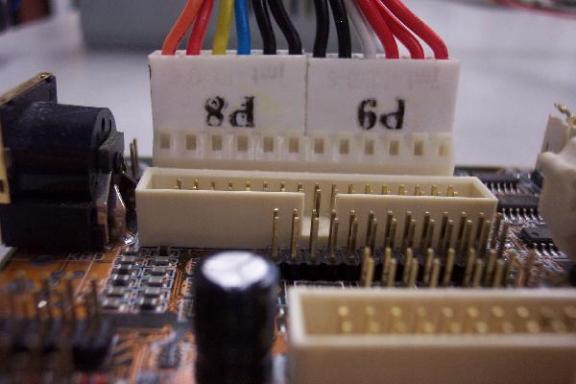
The two AT power supply-to-motherboard 6-pin edge connectors attached "black-to-black"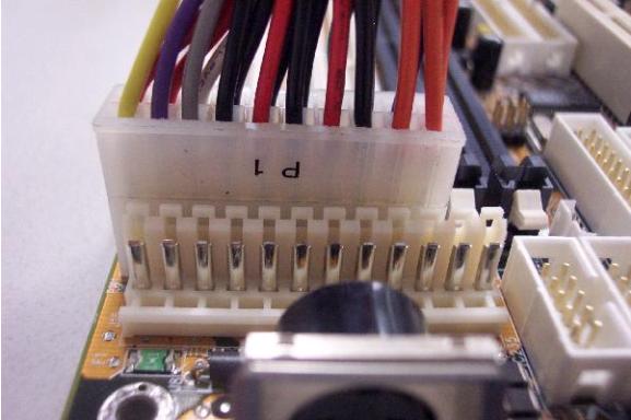
The single ATX power supply-to-motherboard
20-pin keyed connector cannot be reversed by accident -
Because of the fact that the processors and the front side bus motherboard chipset components have different voltage requirements every few months the ATX power supply specification certainly could not change at this rate and the reduced voltage Pentium MMX threatened to render the ATX specification obsolete before it was even ratified. The Socket 7 requirement to include a VRM - Voltage Regulation Module made it so that the ATX motherboard is still responsible for providing voltage regulators that generate the correct voltage for the processor and saved the ATX specification.
-
The first and easiest test of any power supply is the functioning of the fan. If it has failed it can be replaced in many models but the best advice is to replace the whole power supply the logic being that since the circuits have been roasting without cooling for an unknown period of time then they have been subjected to possible latent damage. The life expectancy of the power supplies components has been compromised. Since the remaining life expectancy is an unknown variable, simply replace the device before it fails at the most inopportune moment. With the continual falling prices of the PC industry it is no longer advisable to replace a $5 power supply fan in a $10 power supply either. This is simply not cost effective considering the risk that the power supply is no longer reliable.
-
Unstable power supplies are the single most difficult problem to diagnose. This is why it is so advisable to replace the power supply when its fan has failed. Digital Voltmeters however, are inexpensive and can at least give the stable average output reading on the wires. The industry states that a ±10% deviation of the output voltage on any wire is acceptable. Although the author would personally toss any power supply with any line beyond ±5% deviation. The ATX power supply and digital voltmeters will be covered in depth in later lectures.
-
The features and differences between the two power supply technologies:
Feature AT ATX Physical throw front panel on/off switch Yes No Logic signal front panel on/off switch No Yes Under the control of software/OS No Yes Dual 6-pin edge connectors to motherboard Yes No Single keyed 20-pin connector to motherboard No Yes Pressurizing cooling fan No Yes Depressurizing cooling fan Yes No Fan rotated 90° to move air over the CPU No Yes Generates ±5VDC and ±12VDC Yes Yes Generates +3.3VDC No Yes Deprecated technology Yes No* Sends a POWER_GOOD signal to motherboard Yes Yes Automatically turns off under no load Yes Yes * ATX 1.0 is quickly becoming deprecated in favor of ATX 2.0
-
Standard power supplies are measured in Wattage of power that they can produce. Generally speaking a system with 1 HDD, 1 FDD, and 1 optical drive can usually be driven by a 200 to 250W power supply. However, the P4 processor alone can easily consume up to 70 or more Watts, not counting the rest of the motherboard and the drives. Many consumers are adding additional HDD's and optical drives like DVD-ROM drives and CD-R/RW burners to their systems. Each of these drives is a big power consuming device and such systems will need at least a 400W power supply or better.
-
ATX 2.0 provides two additional sets of 4 power/ground lines to the motherboard. Four of these lines have been added to the ATX power supply-to-motherboard connector making it a single 24-pin keyed connector and the other four lines consisting of two +12VDC and two ground lines are provided by a separate single 4-pin keyed connector.
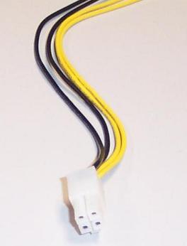
The auxillary ATX power supply-to-motherboard 4-pin keyed connector -
The next set of three components are related such that they must all be chosen together: the CPU, the motherboard, and to some extent the RAM. The most significant choice for the motherboard is that it must be either AT or ATX powered to match the power supply of the system. In modern systems all cases, power supplies and motherboards are ATX so this is no longer an issue. The issue arises when upgrading older systems. Note that all of the components being discussed in this lecture will be dealt with individually in depth so they are necessarily being introduced only briefly now.
-
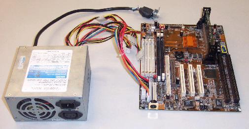
The CPU starting with the Intel Pentium II processor determines the motherboard. This is because Intel trademarked the mounting system of the Pentium II CPU to the motherboard: the SC-242 connector marketed as Slot 1. The Slot 1 connector has a vertically staggered pair of pin rows on each side for a total of 242 card edge connectors within the slot. The CPU, which resembles an expansion card (a Pentium II Celeron chip is visible in a Slot 1 mount in Figure #1), is inserted vertically by pressing it straight down snuggly into the slot. Because Slot 1 is trademarked, competitors (mainly AMD - Advanced Micro Devices) CPU’s cannot be made to fit it without paying a royalty which of course Intel was going to make too expensive to be worth it. So AMD had to make their own unique CPU attachment system to the motherboard. Since these systems are unique and are soldered to the motherboard, this made every motherboard capable of supporting either Intel processors or AMD processors but not both.
-
Prior to the Pentium II and its Slot 1 attachment, systems had been using the Intel Socket 7 design which Intel left as an open architecture technology which meant that AMD processors and Cyrix processors could be made to interface with the Socket 7 freely. Intel closed the door on this because of the excellent quality and low price of the AMD processors in particular which was starting to have an effect on Intel’s market share.
-
Since the Pentium II up to the most recent CPU designs, the mounting systems are unique between the companies meaning that the end-user must first choose the CPU, and then choose a motherboard for it. Because of the schism that began with the Pentium II generation CPU’s, the processors and their chipsets have steadily evolved away from each other to the point that the differences between them are significant.
-
While the processors and the chipsets were evolving away from each other, Intel spearheaded the development of a very high speed form of memory for their processors called RAMBus. RAMBus support was integrated into the Intel motherboard chipset designs which of course supported their processors and not the AMD processors. AMD responded by developing their own high speed memory technology called DDR – Double Data Rate, which was a sophisticated modification of existing memory technology and therefore did not cost nearly as much to develop or manufacture while offering comparable performance. This made the total cost of the PC including the CPU (already cheaper than the Intel), the motherboard, and the RAM memory, even less.
-
Over time third party manufacturers emerged with hybrid chipsets that could support Intel processors using AMD’s DDR RAM. Intel would eventually develop their own chipsets that could do this. So in the modern system it is not necessary to choose all three (CPU, motherboard, and RAM) but for a while these three components were not interchangeable at all. So when upgrading systems it is important to read the documentation of the motherboard at least, to determine what CPU’s and RAM it supports.
-
Many modern motherboards have quite a few integrated peripheral devices. This does reduce the overall cost of building the system, but in many cases the integrated components in the motherboard are of vastly inferior quality to the expansion card versions that are available. As a result of this a “computer-in-a-motherboard” in which all necessary peripherals are integrated such that no expansion cards are even necessary is generally considered an entry-level or beginner’s PC. The high-end, high performance motherboards used to have no integrated peripherals at all but these are becoming hard to find and very expensive (due to the quality of the chipset and manufacture of them).
-
When choosing a motherboard/CPU/RAM combination another factor is the type of expansion bus and number of slots available on the motherboard. In older systems from the Pentium II and prior, motherboards featured ISA – Industry Standard Architecture, expansion card slots (visible as the long black slots to the far right of the motherboard in Figure #1). These expansion card buses allow the user to progressively add more peripherals or upgrade to superior peripherals over time. In the beginning this was done mainly to help defray the initial cost of the computer. These days with the continual and dramatic reduction in prices across the board in the PC industry, there is almost no point to this design any more other than the flexibility of being able to easily upgrade certain components.
-
The original ISA slot on the original IBM PC featured an 8-bit wide data bus as did the CPU and the front side bus to which the CPU attaches. With the IBM AT, which was redesigned in many significant areas to accommodate the much more powerful and faster Intel 80286 CPU, the data bus width throughout the system was expanded to 16-bits including the ISA bus. The slots have a second part or extension so that the first part is still physically identical to the original 8-bit ISA slot to accommodate older 8-bit ISA cards. This process of improvement while still supporting older hardware and software is called backwards compatibility and this is the cornerstone of the PC’s success. Note that even though the motherboard and bus architectures were reworked dramatically in the IBM AT, DOS and most applications and many peripheral components would still run on these machines without modification.
-
Beginning with the Pentium era and seen in some 486 CPU based systems built after the introduction of the first Pentiums, motherboards featured a new expansion card bus: PCI – Peripheral Component Interconnect (visible as the short white slots on the middle of the motherboard in Figure #1). This bus was designed from the ground up by Intel as a universal, scalable, high speed, Plug-N-Play, expansion bus that would allow peripherals to take full advantage of the Pentium’s superior front-side bus speed and processing power. The PCI bus is very well separated from the system front-side bus and under quite a powerful and sophisticated controller. In fact, because of this separation and the power of the PCI bus controller, this bus has also been adapted and accepted in the Apple computer company’s personal computers as well. Despite the fact that the bus is well spearated from the front side bus it provides a very high speed attachment for peripheral devices and is often referred to as a "mezzanine bus" or even a "local bus."
-
The PCI bus has run its course in various adaptations and is now (as of the late Pentium 4 based systems) being replaced by the much faster PCI-Express bus. These peripherals are still hard to come by and fairly expensive so the best motherboard to begin with until this situation changes is a board that features both the standard PCI bus expansion slots and the new PCI-Express expansion slots so that the system can start off using the widely available PCI expansion cards and can be later upgraded to the much faster and more powerful PCI-Express cards once they become more widely available and less expensive.
-
Once the motherboard/CPU/RAM combination has been settled upon, the rest of the system can be assembled around it. Almost all modern motherboards use PS/2 keyboard and mouse connectors if they bother using a “legacy” keyboard controller at all. Many modern systems use USB – Universal Serial Bus, for the attachment of the keyboard and the mouse because this Pentium generation external peripheral expansion bus has also become very widely accepted which also means that USB compatible peripherals have become very inexpensive as well. AT motherboard and power supply based systems are also associated with the legacy AT keyboard controller. This is probably why most ATX systems use the PS/2 connector as a way of separating themselves from the older legacy AT based systems. The AT based motherboard features the AT keyboard connector but this keyboard controller has no provision nor connector for attaching the mouse. Therefore the mouse on these systems has to be serial or in Pentium systems that have a USB controller, then it can be USB. Serial mice have become exceedingly scarce to the point that if one fails and the system has a USB controller, it will more than likely have to be replaced by a USB mouse. AT keyboards are equally scarce and they would also have to be replaced by a USB keyboard. On true legacy systems like a 486 AT based system (with no PCI bus) still in service, it might require quite a concerted effort to locate an AT keyboard and/or serial mouse for it.
-
Equipped at this point with the case, power supply, motherboard, CPU, RAM, and at least the keyboard, what else would be needed to startup the system for a boot up test? The system would need a video controller and a monitor at this point. Many modern systems have a video controller built in to the motherboard and it is critical to point out at this time that this controller is attached to a standard expansion bus even though it is physically integrated into the motherboard and is not a removable expansion card. In legacy systems the video controller was integrated into the ISA bus and in 486 based systems many were integrated into the VESA (Video Electronics Standards Association) local bus even if no actual VESA local bus expansion slots were provided. Late 486’s and early Pentiums feature integrated PCI bus video controllers and starting around the time of the Intel Pentium MMX based systems the AGP – Accelerated Graphics Port appeared on motherboards (visible as the short brown slot to the left of the PCI slots in Figure #1). This is a separate high speed expansion slot that functionally appears like a PCI slot to standard software drivers, but it is based on a clock hat is twice as fast as the PCI bus and it is standalone from the PCI bus so that the video controller does not have to compete with other cards data bus traffic. Bear in mind that AGP 1x is twice as fast as PCI, but PCI-Express is many times faster than AGP 8x.
-
Many high-performance name brand motherboards do not include an integrated video controller and allow the user to choose either a PCI or AGP video controller to install on the appropriate bus as an expansion card peripheral. Note (and this is important) that the PC industry is unique from all others in this aspect: the name brands of significance are the component manufacturers while the name brands of the complete systems are of the least significance. To restate, in the PC industry, name brand components are the highest quality and systems constructed from these “shelf” OEM components are the highest performance and the most reliable and stable. On the other hand, name brand complete computer systems such as can be purchased from the store are made from the cheapest generic components that the manufacturer can find (to reduce the cost of manufacture) and are generally speaking of the poorest performance, reliability, quality, and stability. Some very expensive high end models of name brand PC’s are extremely high quality, but a technician can purchase name brand equivalent components and assemble a comparable PC for far less money.
-
Once the video controller has been selected along with a suitable monitor, then the motherboard/CPU/RAM subsystem could be installed into the case and connected to the power supply. The video controller could then be inserted into the appropriate expansion slot (most likely PCI or AGP) and the keyboard could then be plugged in. At this point the system should be turned on to see the BIOS POST screens. Of course without a disk drive installed the system will issue a boot failure error, but it is best to test the system as soon as the bare minimum system has been setup to make sure that it is working. If it were not tested at this point and instead a floppy drive, hard drive, CD-ROM and/or DVD reader, CD-ROM and/or DVD burner, sound card, network interface card, etc, etc were all piled into the system and then upon pressing the power switch nothing happens, then it would all have to be taken apart anyway as the technician tries to determine by process of elimination, what component is causing the problem. It is far better to put it together and easily test the system one component at a time than to disassemble it, handling every component twice rather than once.
-
Modern name brand systems are no longer equipped with a floppy drive, however it is not easy to create a bootable CD-ROM without having a floppy drive installed so that the bootable CD-ROM can be set up by the burning software as a 1.44MB Floppy Drive A: Emulation type. While brand name systems motherboards more than likely do not even have a floppy disk drive controller also referred to as an FDC), many brand name motherboards do, and this should be a prerequisite for purchasing one. In PC Repair Level 3, creating a bootable CD-ROM using 1.44 Floppy Drive A: Emulation will be explored using the Nero CD-ROM burning software package. At this point the floppy drive should be installed. Note that in the next lecture this procedure will be covered in detail.
-
Once the floppy disk drive (also called an FDD) is installed the system should be booted to a bootable floppy disk to ensure that the drive and the BIOS settings will allow it and are all working.
-
Once the floppy disk drive is working, the hard disk drive or HDD should be installed. This process will be fully explored in a subsequent lecture including how to prepare the HDD for the installation of an operating system: Windows 9x or Windows NT/2000/XP in particular.
-
Once the HDD has been installed, the system at this point is fully functional, but virtually all operating systems and software are stored on CD-ROM media for installation. Therefore an optical drive should be installed at this point and support for it must be added to the bootable floppy diskette. This will be fully explored in a subsequent lecture.
-
With modern systems in which the majority of the peripherals are PCI, it is probably best to have all of these devices installed prior to attempting to install a Plug-N-Play operating system. To complete an MPC ’97 compliant system then, a sound card and speaker set should be installed and set up and an Internet connectivity device needs to be installed. The MPC ’97 specification more than likely called for a modem, but with the proliferation of low cost high speed Internet access these would be the last choice. Quite often external xDSL or cable modems are the primary choice and attach to the system either through USB if they are direct standalone systems or they interface the Internet Service Provider’s local connection to the system through a network interface card allowing more than one system to access the Internet. Network interface cards are very inexpensive and allow either external xDSL or cable modem services to interface to the PC and this is the best generic solution and should be installed at this time as well.
-
At this point a working system is complete, but it is not yet MPC '97 compliant. To recap the basic parts list:
- Case – Desktop or Tower, AT or ATX (remember that AT is only included in this discussion because as a repair technician you will be working with them), number and type of available drive bays.
- Power supply – AT or ATX (see note above concerning AT), wattage, number and types of connectors.
- Motherboard – Primarily chosen based on the CPU and RAM and whether it is AT or ATX (see note above concerning AT), north bridge, form factor (i.e. ATX vs. micro-ATX)
- CPU – Probably the starting point when building a system since modern motherboards only support either Intel or AMD processors never both), In order of priority: 1) # of cores, 2) # of levels, speeds, and amounts of cache, 3) FSB throughput. Actual core speed is of NO IMPORTANCE compared to these three features.
- RAM – A secondary consideration since motherboards can now mix and match CPU’s and RAM technologies. RAM itself should be chosen first and foremost: 1) amount, 2) dual-channel (a motherboard feature), 3) speed. If the CPU/Motherboard have a lot of fast cache, then the money can be spent on the amount of RAM instead of its speed.
- Video controller – Either PCI, AGP, or the new (read: expensive for now) PCI-Express. Video cards can range from $10 to $500 in the stores and they come ten times more expensive than this. For Internet browsing the very cheapest video controller can handle it, but for serious gaming or engineering design applications like AutoCAD, serious video chipset processing power will be needed (read: expensive video card)
- Sound card: Usually purchased these days based on number of channels, but also for analog vs. digital (SPDIF) connections to the speakers.
- Input device: Keyboard: AT, PS/2, or USB (see note above concerning AT)
- Input device: Keyboard: AT, PS/2, or USB (see note above concerning AT)
- Input device: Keyboard: AT, PS/2, or USB (see note above concerning AT)
- Input device: Keyboard: AT, PS/2, or USB (see note above concerning AT)
- Output device: Monitor: The monitor should be capable of effectively displaying the video card’s highest resolution and refresh rates.
-
At this point the system can be assembled and booted to make sure that it will at least enter the BIOS. In the early days of AGP, sometimes the system would fail to display anything on screen at this point until a PCI card was installed instead. Then this could be replaced with the AGP card and the system would display the BIOS POST screens properly. The technician should also enter the BIOS Setup Utility during these first startups and get familiar with the various settings and features available. Modern motherboards should no longer have these issues, but the system should be test booted at this point to ensure that everything is properly connected and working. The parts list continues with the bare minimum components to finish building a multimedia PC:
- Floppy Disk Drive – This device is fairly well deprecated and unavailable on virtually all name brand PC’s. It is a good idea to include one on custom built PC’s because it provides an easy method to start the system should the operating system on the HDD get damaged and fail to startup and it also provides one of the best methods for building custom bootable CD-ROMs.
- Hard Disk Drive – No modern PC can function on a day-to-day basis without an HDD to hold and boot up the immense modern 32-bit operating systems. The main choice concerning the HDD will be the interface. Standard ATA/IDE technology is being quickly phased out by the newer and faster SATA technology. This makes the ATA drives quite inexpensive but difficult to replace in the coming year or two. SCSI is a very expensive, robust, and fast bus that can accommodate far more HDD’s than ATA or SATA. It is an impractical alternative for home use or workstation PC’s but it is the technology of choice for network server’s that need a Redundant Array of Inexpensive Disks. RAID’s are hardware or software level coordinated groups of disks that work together to appear to the operating system as a single HDD. If any one HDD fails (some RAID’s support multiple HDD failure as well), the file system and the computer can continue to function as if nothing happened instead of crashing instantly. RAID’s will be investigated in depth in PC Repair Level 3.
- Optical Drive: CD-ROM Drive – At the very least, a modern PC must have a CD-ROM drive in order to read CD-ROMs on which virtually all modern software is shipped for installation. In addition, with the industry making a concerted effort to render the floppy drive deprecated, a CD-ROM writer, more commonly referred to as a CD-ROM burner, is also highly recommended being the only affordable universal media on which a user can store files for physical transport to another computer, or for safe keeping outside of the computer (in preparation for HDD failure)
- Input device: Serial, PS/2 or USB mouse pointing device for interacting with the modern graphical user interface based operating systems such as the Microsoft Windows 9x and NT/2000/XP families.
- Sound card – most PCI cards are either "sound blaster compatible" or AC’97 compatible which appears to be a basic compatibility specification introduced with the MPC ’97 specification. Either type should function with most software.
- Output device: speakers – Speakers can range from a $5 unamplified pair to many hundreds of dollars. For that much power it is best to purchase an adapter cable and run the sound card’s output to a home stereo system.
- I/O device for Internet connectivity: PSTN modem/xDSL modem/cable modem – These days external modems with standard Ethernet interfaces are so common and inexpensive (often provided for free with the high speed Internet service contract) that the most affordable and universal adapter that can be installed is a standard Fast Ethernet network interface card.
- Interconnectivity cables: not specifically mentioned so far but absolutely essential to constructing the system will be: standard 34-pin floppy drive data cable, either a standard 40-wire/40-pin IDE cable of the modern “UDMA” cable (80-wire/40-pin IDE cable), a second 40-pin IDE cable for the secondary controller, a CAT5e Fast Ethernet cable for connecting the network interface card to the xDSL modem/router (or cable modem/router), an MPC compliant sound cable that attaches from the CD-ROM reader to the sound card. This cable allows the CD-ROM drive to detect the insertion of a standard CD-a (CD-audio) disc and begin playing it. If the cable is attached it will send the sound stream through this cable directly to the sound card for amplification and output to the speakers thus bypassing the computer altogether. By removing the digital processing of the audio CD from the buses and the CPU a large amount of work is easily offloaded and the user can listen to audio CDs without placing any extra processing burdens on the system.
-
In a subsequent lecture a standard ATX based PC will be assembled using the basic parts list outlined here. Note that many of the subsystems and components included in this outline will be addressed individually in the upcoming lectures as well. This lecture is intended to provide a basic outline of the entire system and the parts list that can be followed to build a basic home user PC. At times, differences will be pointed out where subsystems may depart radically for the support of high end engineering workstations as well as network servers.
Review Questions
-
Explain why the MPC ’97 Specification was developed.
-
Name the two basic physical case types and explain how the original type was modified into the second type.
-
List two reasons why the tower case became much more popular than the desktop case type.
-
In the PC an item often has more than just its physical dimensions involved in its physical design, its physical construction will also follow specifications for the locations of screw holes as well as electrical connector types and positions and so on. This is called the item’s:
-
List and describe the two case power supply based form factors available in 1997 and which one is currently deprecated.
-
Define “deprecated”:
-
Upon removing the case cover of a computer what is the most obvious way to identify whether the power supply is AT or ATX?
-
What type of physical front panel power switch does the AT power supply use? and what type of front panel switch does the ATX power supply use?
-
What is the main functional difference between the AT and the ATX power supply?
-
While designing the ATX power supply based system what was done with the cooling fan of the power supply in the ATX? What is the cooling system of each type of power supply called?
-
The ATX pressurized cooling system is thought of an advantage. Explain why and explain why it can also be a disadvantage.
-
What change was made to the ATX power supply to motherboard connector that made it much less likely to contribute to accidental destruction of the motherboard by novice PC builders? Describe the standard AT and ATX connectors.
-
What new voltage does the ATX power supply provide and what was this provided for? Despite the fact that this voltage was added to the ATX specification it is no longer used. Explain why and what must be added to the motherboard anyway.
-
What is the first and easiest test of a power supply?
-
In the event that the power supply cooling fan has failed give three reasons why the entire power supply should be replaced rather than just the cooling fan.
-
Based on the feature chart list the features that both the AT and ATX have in common.
-
What three major components must be selected together for physical compatibility reasons?
-
What was the first Intel CPU to feature a trademarked mounting system to the motherboard that prevented competitors from manufacturing replacement CPU’s and what was the part number and its marketing name?
-
What was the CPU mounting system that preceded Slot 1 that competitors could make CPU’s for royalty free?
-
What is the term used commonly in the PC industry when a technology is developed by a company and then made available for all competitors to use freely?
-
Since the CPU’s were no longer compatible, what group of components soldered to the motherboard began to evolve away from each other?
-
What was the new high speed RAM memory technology called that was developed by Intel for their specific CPU’s and motherboard chipsets?
-
What was the new high speed RAM memory technology called that was developed by AMD for their CPU’s and motherboard chipsets?
-
If a motherboard has all necessary peripherals devices integrated into it, it is
generally considered to be intended for ________________________ users.
-
Name brand motherboards generally have few if any integrated peripheral devices are
generally ________________________.
-
Name the first internal expansion bus used in the PC that features long black slots on the motherboard for expansion cards.
-
Name the newer high speed universal Plug-N-Play internal expansion bus developed by Intel to take advantage of the computing power of the Pentium processor.
-
The PCI bus is well separated from the front side bus. Because of this separation from the front side bus, what totally incompatible computers also feature PCI?
-
What new high speed internal expansion bus is beginning to replace PCI?
-
What is the term used in the PC industry when a new technology is developed that allows existing hardware and/or software to still be compatible and function with little or no modification required?
-
Because the AT keyboard connector is associated with the AT power supply/motherboard based systems, what is the legacy connector used by ATX motherboards and what other peripheral can be attached to this keyboard controller?
-
Name the three types of standard keyboard interfaces.
-
Name the three types of standard mouse interfaces.
-
Video controllers that are integrated into the motherboard are still attached to one of
the standard __________________________.
-
A video controller integrated into a 486 motherboard might interface through this standard expansion bus even if there are no physical slots available.
-
Starting around the MMX generation of Pentium processors this new expansion slot was developed specifically for video cards.
-
The AGP port is similar in size to a ___________ slot but usually brown and further from the back of the motherboard than they are.
-
An integrated video controller on a Pentium II motherboard could be attached to hich two expansion buses?
-
In the absence of specific drivers for an AGP card it can still function in a rudimentary
fashion because the slot appears to the generic drivers as if it was a ________ expansion bus slot.
-
List all of the components necessary to be assembled to perform the first startup that will be capable of displaying the BIOS POST and can enter the BIOS Setup Utility.
-
Name two good reasons for including a floppy disk drive on a modern custom built PC:
-
Name the three modern hard drive technologies that can be chosen and specify which one is the fastest, most reliable, supports the most HDDs and is the most expensive.
-
SCSI controllers and hard drives are most often seen on network servers mainly because they support large numbers of drives which can be set up as a:
-
Which hard drive technology of the three currently available will be the first to become deprecated soon?
-
What kind of drive can be installed on a modern system that will allow the user to backup files to a removable media and allow the user to physically transport files to another system? (The best choice based on it being affordable and universal)
-
A mouse is necessary on modern PC’s to support the __________________________ of virtually all modern operating systems.
-
Name two peripheral components that have not been mentioned in these questions yet, which complete the MPC ’97 capabilities of the PC but are not necessary for the PC to work.
-
What is the most generic Internet connectivity device that can be installed on the modern PC?
-
Rather than purchase a very large amplifier and speaker set for the PC, the sound card
should be attached to ____________________ with a _____________________.
-
The FDD is attached to the system with a data ribbon cable with how many wires in it? This cable attaches the FDD to what peripheral?
-
The standard IDE cable has how many pins in the connectors? How many wires in the cable?
-
The standard UDMA IDE cable has how many pins in the connectors? How many wires in the cable?
-
An MPC type sound cable is used to attach the CD-ROM drive directly to the:
-
The MPC type sound cable allows the user to ___________________ without placing any extra data processing burdens on the system.
-
What peripheral component discussed above has the widest new shelf box price range?
-
If the computer is intended for a beginner who would like to browse the Internet but not
play any full screen animation video games any of the _______________ video cards available will do.
-
If the computer is intended for use playing full screen animated video games or
engineering applications such as ______________ then an expensive video controller will be needed.
Copyright©2000-2004 Brian Robinson ALL RIGHTS RESERVED