CET1171 Lecture #9 - The PC BIOS and the Boot Sequence

Materials:
Working complete PC
Blank Diskette
Motherboard Manual
Student Diskette, "New Boot A Ver 2.0+"
Objectives:
Be able to determine how to enter the BIOS Setup Utility
Understand the hardware and software components of the system BIOS,
Identify the BIOS EEPROM
Determine the BIOS Serial # and Manufacture Date,
Identify and Replace the BIOS Battery,
Understand the System Boot Sequence,
Configure the System Boot Sequence,
Configure the Standard Settings, BIOS Features, Integrated Peripherals,
Clear the CMOS using hardware and software techniques.
Competency:
The student understand the role of the system BIOS and the function of the hardware components of the system BIOS including the EEPROM, RTC clock chip, and the BIOS battery. The student will understand the PC boot sequence and how to control it. The student will understand the function of the four major subsections of the BIOS code and be able to enter the BIOS Setup Utility and use it to properly configure the system for hardware and operational changes. The student will learn how to identify the specific BIOS installed in the system and also be able to clear it using both hardware and software techniques.
  1. The student will need a system unit, monitor, and keyboard fully setup and working. The student will turn the computer system on. This is often referred to as booting up the system. When using the power switch or reset button, this is referred to as a cold boot. Historically, the reason for this name is that the current was absent so the system components were "cold" when the power switch was activated.

  2. Once the system has successfully booted up, press and hold the [Ctrl] key. While holding this key down, press and hold the [Alt] key, while holding both of these keys down, press the [Delete] key and release all three keys. The [Ctrl]+[Alt]+[Delete] key combination has always been wired into the PC's keyboard and motherboard architecture to reboot the system whenever it became unstable. There are many names for this instability: crashed, locked up, frozen, hung, blue screened, blue screen of death (especially with Windows NT). Rebooting a PC using the [Ctrl]+[Alt]+[Delete] key combination is referred to as a warm boot. This is because the PC is on and the circuits are all active and therefore "warm" when this is done.

  3. There are subtle differences in what the PC does in a cold boot versus a warm boot. The main difference lies in the POST or Power-On Self Test of the BIOS. In a cold boot the PC will check all immediate and critical devices and count and test all of RAM, in a warm boot, several phases of the POST are truncated and the RAM is not tested at all. In order to ascertain the amount of RAM in the PC, the technician must cold boot the system. Do so now by turning the system off using the power switch. Wait 10 seconds and then turn the power back on. You should always wait 10 seconds because it takes this long for some of the active circuits to completely drain their electrical energy and return to a normal state for being powered up again. Forcing these circuits to take electrical current before they have reached a stable "off" state can severely reduce their life expectancy if not immediately damage them. Make a note of the amount of RAM on the system according to how much RAM the cold boot POST counts up. Record this at the end of this lesson.

  4. The Pentium MMX based systems in this exercise use generic motherboards that have a generic industry standard BIOS installed on them. The BIOS - Basic Input/Output System, is a set of programs and program subroutines that are stored on a ROM - Read Only Memory chip installed on the motherboard. Since the Intel x86 family processors always reset their Code Segment and Instruction Pointer registers to the values F000h:FFF0h which maps to the physical address of FFFF0h then if a ROM chip were mapped to this address, then the CPU could immediately begin executing the instructions located there. This could be a program that contains enough information to be able to read the drives and load the operating system off of them into memory and this is exactly what takes place. But there is a lot more to the BIOS than just this BIOS Boot Strap Loader code mentioned here so far.

  5. The BIOS is software stored on a permanent memory chip attached to the motherboard. The modern chip used is refered to as an EEPROM - Electrically Erasable Programmable Read Only Memory. The original ROM chip had to be manufactured with the program code. If there was mistake (bug) in that code, then all of the chips manufactured with it would be useless. The next generation of ROM chip developed was the PROM - Programmable Read Only Memory chip. These could be manufactured blank and then be mounted on a rather expensive PROM burner board that would write the program code to them. Once written they could not be erased. So if a discovery was made that the code had a bug in it at a later time, then all of the chips would be useless and have to be discarded. The next generation of ROM chip was the EPROM - Erasable Programmable Read Only Memory chip. These are manufactured blank and can be programmed with the PROM burner. They can also be removed from their circuit board and be placed in a special and expensive ultraviolet oven where they are subjected to intense ultraviolet rays which erase the chip. It can then be placed on the PROM burner again and be programmed with new program code. The latest variation of ROM chip present on virtually all modern Pentium class PC's is the EEPROM. This one is like the EPROM except that it can be given a normal electronic pulse that can erase it. It can then be rewritten with new program code. Modern motherboards include the circuitry that can both erase the chip and reprogram it without having to remove it. This requires an EEPROM chip and the motherboard manufacturers refer to this type of design in which they have mounted the EEPROM directly into a socket that allows the standard system bus to access it (allows the CPU to execute its instructions like normal RAM) and also allows it to be erased and rewritten without having to remove it as flashBIOS. The two terms are not exactly interchangeable: flashBIOS is the circuitry design of the motherboard that allows the chip to function like RAM and also provides the ability to erase and reprogram the EEPROM in place as well as the EEPROM itself. The EEPROM is simply the actual chip on which the BIOS code resides.

  6. In addition to the motherboard support circuitry, the BIOS hardware consists of the EEPROM chip which is usually a standard DIP IC chip that is socket mounted for easy removal. This is done because if the chip ever gets permanently damaged then the system cannot execute the instructions necessary to launch the OS and would therefore be completely ruined and unusable. The BIOS hardware subsystem also includes the RTC, Real Time Clock chip. This peripheral was added to the motherboard design of the IBM AT. This chip is a small clock/calendar chip like the one that runs such digital clocks like wrist watches. The chip is not manufactured out of silicon but rather a sandwich of rare earth metal oxides which also happens to have semiconductor properties. This manufacturing material and the chips made from it are all refered to as CMOS - Complementary Metal Oxide Semiconductor. The fourth hardware component of the BIOS subsystem is the BIOS battery.

  7. The RTC chip is often refered to by this name when refering to the standard peripheral component which keeps the date and the time in the PC. This chip runs off of a small battery attached to the motherboard which is why the system does not lose track of the date and time even when it is turned off. CMOS material is used in these chips because it has a very low power consumption requirement and some RTCs will keep the correct date and time even when unplugged for many months. The RTC chip however does much more than just keep the date and time. This chip also holds 64 bytes of RAM in the original design used by the IBM AT. In later models an RTC chip was employed that had 128 bytes of RAM built into it and the latest AT-type systems included an RTC with 256 bytes of RAM. The PCI equipped system could have an extended area with megabytes of additional storage space in this RAM area for holding the PCI bus device settings called the ESCD - Extended System Configuration Data. In the case of the standard (usually 256 bytes) RTC RAM this is refered to as the CMOS RAM of the system.

  8. CMOS RAM built into the RTC is not directly addressable like normal RAM nor even the EEPROM by the CPU and is instead built into the RTC device. This device must be sent requests to read or write to each location as needed. These RAM locations are where the specific settings of the installed hardware on the system are stored. They are stored here because the chip runs off of the battery when the system is turned off or even unplugged. This allows the system to retain critical hardware settings even when power is interrupted in any way. Otherwise the system would have to be reconfigured (exactly the same) every single time the system were turned on.

  9. Open the case of the system and begin exercising proper anti-ESD procedures. Find the EEPROM and the battery on the motherboard. Using a copy of the motherboard manual identify the clear CMOS jumper on the motherboard and read exactly how to use it to clear the CMOS settings.

    Example Motherboard Manual Page

    Clear CMOS – JP20
    The jumper JP20 can be used to clear the CMOS memory of the mainboard. This jumper will clear the CMOS data stored in the Intel 371AB chip. To clear this data follow these steps:

    1) Turn off the computer
    2) Remove jumper from
       JP20 Pins 1 and 2
    3) Insert jumper on Pins
       2 and 3 for a while.
    4) Remove jumper from
       Pins 2 and 3
    5) Reinsert jumper on
       Pins 1 and 2
    6) Turn on the computer


    The actual jumper on the motherboard
    described in the manual page above
  10. When doing this, the CMOS RAM locations onboard the RTC are overwritten with zeros or allowed to "bounce" by being cutoff from the battery which leaves all locations holding random values. Clear your system's CMOS using the jumper. Be sure to set the jumper back to normal operational mode. Replace the system case and power on the system.


    Moving the Clear CMOS jumper on the motherboard
  11. The four main software components of the BIOS program code are: the POST - Power On Self Test, the BIOS Boot Strap Loader, the BIOS CMOS Setup Utility, and the BIOS built in 16-bit device drivers for all standard peripheral components.

  12. The POST code starts by scanning for offboard BIOS'es and if it finds any it will immediately pass control to them. After control returns to the POST it will test all of the immediate chipset members that are in direct contact with the CPU and upon which it depends such as the Dynamic RAM controller which organizes RAM banks and controls the refresh of the RAM memory cells and the relocatable address demultiplexing. Another close and important chip is the expansion bus controller. The POST proceeds on to test the peripheral devices attached to the expansion buses. The POST is following industry standards such that every DRAM controller is supposed to receive a specific instruction from the CPU on a specific I/O address and when it receives this it is supposed to set a specific value at an I/O address for the CPU to read. All standard PC devices have these well defined I/O port addresses and command sets. The POST command sent to each device basically means “respond to this” or “are you alive?” When the device recognizes this command it responds to it according to the standard so that the POST program code can read the port and match the value against what it expects according to the standard. This response from each device can be thought of as meaning “Yes, I am alive!”

  13. So if all of the devices respond properly then the system has successfully passed the POST and then the POST will issue a single beep from the system speaker and then the POST code will jump to the next embedded program component of the BIOS code: the BIOS Boot Strap Loader code.

  14. This program will access the CMOS Hardware Configuration settings stored in the CMOS RAM, specifically it reads the CMOS boot sequence stored there. It will then attempt to boot from each device in order. The BIOS boot strap loader code will access the local disk drives at the low level through the 16-bit low level device driver components that are also part of the BIOS code. This means that a hardware manufacturer can design whatever floppy disk drive controller they want and it can have any command set they want except that the controller must understand and respond correctly to the POST query. The commands to access the attached floppy disk drives and how this is done can be unique to the device. However, the details of getting a sector from a floppy are embedded in the BIOS low level device drivers such that a program can call the embedded BIOS driver code to fetch a particular sector from the floppy drive and then this embedded code will handle the low level details of sending the appropriate commands to the device and handle the timing and status codes coming from the device and ultimately deliver the sector to the calling program. This allows every PC to have unique low level hardware but the higher level programs do not have to know about the details of this hardware or how to access it. They will instead make a standard BIOS call and the BIOS written specifically for that motherboard and its devices will handle it.

  15. So the BIOS Boot Strap Loader will make a call to the BIOS function to read a sector from the boot disk drive. The sector will be delivered into RAM by the low level device driver code and the BIOS Boot Strap Loader code will inspect it. If it is structured properly it will execute a jump instruction setting the cs:ip pair equal to the location where the sector was placed into RAM. This allows the program that was written to this sector of the disk drive to execute.

  16. At this point the direct execution of BIOS program code ends and the operating system programs loaded into this sector and beyond proceed to load the operating system from their locations stored on the drive and into RAM memory where they begin executing and controlling the computer for the user.

  17. The BIOS 16-bit device drivers present other software a universal set of functions for accessing standard devices built into any motherboard regardless of how that hardware specifically works. This is called the BIOS API - Application Programmer's Interface which IBM published so that anyone could write software that would work on any PC. However, the BIOS functions are very limited and very low level. They will deliver a specific physical sector from a hard drive, but certainly not a file, for example. Early operating systems like DOS used the BIOS API to access the physical devices. Because of this, they could run on any PC, since the BIOS API was standardized across all PC's. The operating system then offered its own set of low level published functions for software developers to use, the operating system API. Because the operating system organizes information within a hard drive partition using a file system, information within the file system can be organized into files with user-friendly names that are easy to remember and the OS API allows software to refer to these file names rather than having to retrieve the information by remembering low level sector coordinates. The OS then translates the file name into these low level coordinates using its file system references which then use the BIOS API to actually retrieve the data which it then delivers whole to the software. So wherever the BIOS API works, the operating system will work, and wherever it works, the software will work. This is what made software development relatively easy, and universally compatible on any PC. Even to this day, the old BIOS reliant software works decades later.

  18. The BIOS Setup Utility is a menu driven program built into the BIOS code which allows the user to inspect and modify the hardware configuration settings held in the CMOS RAM. This program section of the bIOS normally does not execute during a routine start up. During the POST of the system you can enter the BIOS CMOS Setup Utility by pressing the correct key or combination of keys. Whenever the system detects a hardware configuration error either because the CMOS RAM settings have been corrupted or because the hardware physically installed does not match what the POST discovered, then the system will either issue a POST error message on screen and invite the user to enter the BIOS Setup Utility or it will automatically enter the Setup Utility.

  19. Having cleared the CMOS, the system will report a "CMOS checksum failure" POST error message on screen and present you with the choice to continue the boot process or to enter the BIOS Setup Utility. Enter the BIOS Setup Utility. Here is the main screen of the Award BIOS that is used on the motherboards of the PCs in Room 6360:

    ROM PCI/ISA BIOS (2A59IH2H)
    CMOS SETUP UTILITY
    AWARD SOFTWARE, INC.

          STANDARD CMOS SETUP
          BIOS FEATURES SETUP
          CHIPSET FEATURES SETUP
          POWER MANAGEMENT SETUP
          PNP/PCI CONFIGURATION
          LOAD BIOS DEFAULTS
          LOAD SETUP DEFAULTS
          INTEGRATED PERIPHERALS
          SUPERVISOR PASSWORD
          USER PASSWORD
          IDE HDD AUTO DETECTION
          SAVE AND EXIT SETUP
          EXIT WITHOUT SAVING
          

     Esc : Quit
     F10 : Save & Exit Setup

          : Select Item
     (Shift)F2 : Change Color


    Time, Date, Hard Disk Type...

  20. Press [Enter] with the choice Standard CMOS Settings highlighted. These settings are the most common ones and date back to the original IBM AT and can be found on almost any system's BIOS Setup Utility. Here you can manually enter the Date and the Time. Since clearing the CMOS reset the date to Jan 1, 1980 (the oldest date that a PC can be set to) and midnight of that date, set the correct time and date now. This screen can also be used to manually configure the hard drives attached to the motherboard ATA (IDE) controllers. However, this should only be done in the event that a particular translation is required. Otherwise the system can be left to "autodetect" them which will configure then correctly and with the optimal settings to take advantage of the drive's advertized size and capabilities. Here the system cn also be configured for the floppy disk drive that is attached to it. The default is setting is: Drive A: 1.44M 3½". Change this to "None" and set Drive B: to 1.44M 3½". Here is the Standard CMOS Settings screen:

    ROM PCI/ISA BIOS (2A59IH2H)
    CMOS SETUP UTILITY
    AWARD SOFTWARE, INC.

          Date (mm:dd:yy) : Wed, May   5  2004
          Time (hh:mm:ss) : 9 : 38 : 45
       HARD DISKS      TYPE  SIZE  CYLS  HEAD  PRECOMP  LANDZ  SECTOR  MODE
      
       Primary Master: User 2112 1023 64 0 4091 63 LBA
       Primary Slave: None 0 0 0 0 0 0 ----
       Secondary Master: None 0 0 0 0 0 0 ----
       Secondary Slave: None 0 0 0 0 0 0 ----

      Drive A : 1.44M, 3.5 in.
      Drive B : None

      Video : EGA/VGA
      Halt On : All Errors
    Base Memory:
    Extended Memory:
    Other Memory:

    Total Memory:
    640K
    31744K
    384K

    32768K


    Esc : Quit              :
    F10 : Save & Exit (Shift)F2:


     Select Item
     Change Color


    PU/PD/+/- :


    Modify

  21. Having made these changes press [Esc] to return to the main menu. From this screen highlight and enter the BIOS Features Setup Screen which looks like this:

    ROM PCI/ISA BIOS (2A59IH2H)
    CMOS SETUP UTILITY
    AWARD SOFTWARE, INC.

    Virus Warning
    CPU Internal Cache
    External Cache
    Quick Power On Self Test
    Boot Sequence
    Swap Floppy Drive
    Boot Up Numlock Status
    Boot Up System Speed
    Typematic Rate Setting
    Typematic Rate (Char/Sec)
    Typematic Delay (Msec)
    Security Option
    PCI/VGA Palette Snoop
    OS Select For DRAM > 64MB

    :Disabled
    :Enabled
    :Enabled
    :Disabled
    :CDROM,C,A
    :Disabled
    :Off
    :HIgh
    :Disabled
    :6
    :250
    :Setup
    :Disabled
    :non-OS2

    Video BIOS Shadow
    C8000-CBFFF Shadow
    CC000-CFFFF Shadow
    D0000-D3FFF Shadow
    D4000-D7FFF Shadow
    D8000-DBFFF Shadow
    DC000-DFFFF Shadow

    : Enabled
    : Disabled
    : Disabled
    : Disabled
    : Disabled
    : Disabled
    : Disabled


    Esc:Quit      
    F1 :Help      PU/PD/
    F5 :Old Values (Shif
    F6 :Load BIOS Defaul
    F7 :Load Setup Defau

    :Select
    +/−:Modify
    t)F2:Color
    ts
    lts


  22. On this screen be sure that Virus Warning is enabled for now. This feature functions by monitoring the BIOS own software 16-bit device driver that can be called by DOS or programs to perform a low level read or write of sectors to either the floppy drives or the hard drives. If a call is made to write to the first sector of the hard drive, the Master Boot Record, then the BIOS will stall the operation and display a warning on screen that this is taking place. Leaving it enabled, we can see how this works by running FDISK later, which of course creates partition tables in the master boot record. Also be sure that the Quick POST and the Swap Floppy Drive settings are disabled. The quick POST saves a few seconds during boot up but on these motherboards it does not allow the boot strap loader sufficient time to properly initialize the CD-ROM drive if you wish to boot from it.

  23. Set the Boot Sequence to: A,C,SCSI. This is the choice that most resembles the original boot sequence of first the floppy disk in Drive A: then the first hard drive. This BIOS allows control to be passed off to a SCSI controller that has an onboard BIOS of its own that can handle booting off of the SCSI hard drive(s) attached to it. It should be noted that the first thing the POST does is search for external BIOS'es installed on peripheral components, if any offboard BIOS'es are detected it will immediately pass control to these one at a time in the order in which they are found, before actually starting the POST. Video controllers usually have their own BIOS that will be allowed to initialize before the motherboard POST begins, this way they can reset the video card so that output to the screen will be viewable.

  24. The PC boot sequence was originally fixed as first the A: drive, then the first physical hard drive. But as the system evolved, more peripheral devices have become "bootable" or capable of booting up the system but providing a properly installed operating system on them. As a result, modern BIOS CMOS settings allow the user to change the boot sequence to allow the BIOS boot strap loader to attempt to load the first physical sectors from these different devices in different orders. However, the student should know the complete boot sequence of the PC:

    1. POST passes control to any external BIOS(es) found.
    2. POST proceeds.
    3. BIOS Boot Strap Loader checks CMOS Setting Boot Sequence, proceeds to attempt to boot from each device in the order listed there, by reading the first physical sector of each device and checking it to see if it is "good."
    4. If the BIOS boot strap loader finds a "good" first physical sector of the hard drive called the MBR, it will load it into RAM and pass control to it.
    5. The MBR holds the Operating System 1st Stage Boot Strap Loader Code, which will read the first sector of the "active" partition called the VBR - Volume Boot Record, into RAM, check it, and if it is "good" pass control to it. The MBR and VBR are software that has to be written to the HDD by an operating system utility.
    6. The VBR will load the first file from the partition's file system into RAM, check it and then pass control to it.
    7. The first file of the operating system is now functioning and it will continue loading the rest of the operating system until it is up and running.

  25. Press [Esc] to return to the main menu screen and then highlight the choice Integreated Peripherals and press [Enter].

  26. Here is the Integrated Peripherals screen:

    ROM PCI/ISA BIOS (2A59IH2H)
    CMOS SETUP UTILITY
    AWARD SOFTWARE, INC.

    IDE HDD Block Mode
    IDE Primary Master PIO
    IDE Primary Slave PIO
    IDE Secondary Master PIO
    IDE Secondary Slave PIO
    IDE Primary Master UDMA
    IDE Primary Slave UDMA
    IDE Secondary Master UDMA
    IDE Secondary Slave UDMA
    On-Chip Primary PCI IDE
    On-Chip Secondary PCI IDE
    USB Keyboard Support

    KBC input clock

    :Disabled
    :Auto
    :Auto
    :Auto
    :Auto
    :Disabled
    :Disabled
    :Disabled
    :Disabled
    :Enabled
    :Enabled
    :Disabled

    :8 Mhz

    Parallel Port Mode

    : SPP

    Onboard FDC Controller
    Onboard Serial Port 1
    Onboard Serial Port 2
    UR2 Mode

    Onboard Parallel Port

    :Enabled
    :2F8/IRQ3
    :Auto
    :Standard

    :378/IRQ7

    Esc:Quit      
    F1 :Help      PU/PD/
    F5 :Old Values (Shif
    F6 :Load BIOS Defaul
    F7 :Load Setup Defau

    :Select
    +/−:Modify
    t)F2:Color
    ts
    lts


  27. Note the setting for "Onboard FDC Controller" as enabled or disabled. If you disable this onboard floppy drive controller then obviously it does not matter what you set Drive A: or Drive B: to on the standard settings screen, the controller will be turned off and will not be able to access any floppy disk drive. Also note that the serial and parallel ports can be configured here. All of these devices are standard devices on the IBM AT and they are attached to the old ISA bus and are not considered plug-n-play peripherals. In MSM2 you will learn what these settings are, what the industry standard assignments are and how to change these settings properly. Press [Esc] to return to the main menu and then select Save and Exit and press [Enter], in the warning dialog box, type [Y] and press [Enter] again to confirm the saving of these changes that have been selected in the Utility to be written to the CMOS RAM locations onboard the RTC chip. At this point the system will attempt to reboot. Turn it off and change the attachment of the floppy drive from Drive A: to Drive B: Now turn the system back on again.

  28. At the DOS Prompt attempt to read a diskette in Drive B: Format a blank diskette in drive B: and make it bootable. Restart the PC and see if it will boot from the bootable diskette. You can see that under no circumstance will a PC boot from the B: drive.

  29. Reenter the BIOS and change the Floppy Drive settings back so that the system will recognize the Drive A: as a 1.44M 3.5 in. and set Drive B: to none. Save and Exit. Allow the system to reboot to the bootable floppy. Will it? Turn the PC off and change the physical cable attachment of the floppy disk drive back to Drive A: Restart the PC, will it boot to the floppy? Reboot and enter the BIOS. Go to the Integrated Peripherals screen and disable the Onboard FDC controller. Save and Exit. Will the system boot to the bootable floppy disk now? Will it read the floppy at all? Reboot, Enter the BIOS Setup and reenable the Onboard FDC. Enter the BIOS Features screen and set the boot sequence to C,A,SCSI. Save and Exit. Will the system boot to the floppy diskette now? The only way that a floppy can startup the system when listed after the hard drive is if the hard drive does not deliver its first physical sector or that first physical sector fails the BIOS boot strap loader check (for being "good").

  30. Reboot the PC and during the RAM count press the [Pause] key (it is above the Page Up key) With the screen paused, record the BIOS manufacturer name, BIOS version, motherboard model, motherboard chipset, CPU, total amount of memory, the keystroke needed to enter the BIOS Setup Utility, and the BIOS date/serial number all of which are on screen at this time (you may have to press [Pause] again to allow the memory count to proceed to the top of memory so that you can tell how much is installed)

  31. Using one of the spare "dead" motherboards in the room practice proper anti-ESD by grounding the motherboard to one of the working systems in the room by attaching the "P8" and "P9" AT power supply to motherboard connectors to it. Clip your wrist strap to the system case that you are using and put it on. Practice removing the CR2032 type BIOS battery and then replace it. By removing the CMOS battery in most, but not necessarily all cases, the CMOS RAM will be cleared. This is the preferred method only when the clear CMOS jumper can either not be identified or the method of using it cannot be determined. Another issue is the fact that the motherboard may have a "failsafe" design in which a capacitor or even a second battery on the motherboard prevents the CMOS RAM from being lost when the conventional removable battery is replaced. On these systems it could take months for the second battery to drain. In this case it is preferred that you find the motherboard jumper settings on the Internet and use the clear CMOS jumper.

  32. Now the CMOS RAM will be cleared using the DOS utility DEBUG.EXE. If the PC will boot up to a DOS prompt (either from the HDD or from a floppy) then by all means the most prefered method of clearing the CMOS is through software. There are utilities, most of them freeware, that will clear the CMOS. The executable KILCMOS.COM on "New Boot A:" will clear the CMOS and a technician should know how to run DEBUG and then enter the following commands at the DEBUG dash prompt in order to clear the CMOS also:

    C:\>debug
    -o 70 17
    -o 71 17
    

    At this point the CMOS RAM has been modified and the checksum will fail causing the BIOS to automatically assume that no information within the CMOS RAM is valid and it will therefore ignore the fact that there is a BIOS Setup Utility password. Reboot, there is no need to exit DEBUG, and see if the DEBUG instructions succeeded in clearing the CMOS. The two main reasons why the techician would want to clear the CMOS values is because there is a BIOS Setup password preventing the user from entering the BIOS Setup in order to change a setting, or it has become corrupted and the system fails to boot up even to allow the user to enter the BIOS Setup to change the corrupt or faulty setting.

Review Questions

  1. What is the first address that the x86 family of processors will always begin executing from when powered on or power reset? Give the segment offset notation and the physical address.


  2. What is the basic kind of memory chip installed at this address?


  3. A ROM chip that is manufactured blank and can be programmed one time only is a:


  4. A ROM chip that can be programmed a number of times and is erased by high intensity ultraviolet radiation is called a:


  5. A ROM chip that can be programmed a number of times and can also be erased with a circuitry signal so that it does not have to be removed from the motherboard is called a:


  6. The motherboard manufacturers refer to the EEPROM technology as:


  7. What two expensive pieces of equipment did the EEPROM effectively eliminate from the end user cost of updating the BIOS?


  8. What is the purpose of the BIOS?


  9. How does the system know how to find the BIOS code when it first boots up?


  10. Record all values from the Paused POST screen here:

    BIOS manufacturer:
    BIOS version:
    Motherboard model:
    Motherboard chipset:
    CPU:
    Total amount of RAM:
    To enter the BIOS:
    BIOS date/serial:
  11. List and describe the four hardware components of the BIOS subsystem on the modern motherboard:


  12. List and describe the four software components of the BIOS:


  13. The CMOS is not a chip but the ___________________ from which the chip is made.

  14. CMOS means:


  15. The CMOS RAM holds the system's:


  16. The CMOS RAM is actually a feature of what peripheral component?


  17. What is this peripheral's designed purpose (other than the CMOS RAM it contains)?


  18. How does the system “know” the correct time and date even when it has been unplugged, even for weeks?


  19. How does the system “know” that it has a 1.44MB 3 ½” floppy A: drive and a certain type of hard drive, etc.?


  20. How does the system retain these hardware configuration settings even when it has been unplugged for weeks?


  21. The CMOS settings include a boot sequence setting, in order to be sure that the system will boot to a bootable floppy diskette if it is present in the A: drive the choice must at least list the A: drive:


  22. Even though the floppy disk drive was attached properly as the B: drive and was correctly configured in the BIOS as the B: drive and could format bootable floppy diskettes and was fully

    functional the system would never ______________ from a diskette in this drive.

  23. If the onboard FDC controller is disabled in the motherboard BIOS, what functionality of the A: or the B: drive(s) is lost if any?


  24. The built in BIOS Virus Warning feature is no substitution for a fully functional anti- virus package because it does not possess a virus list. Instead all it does is:


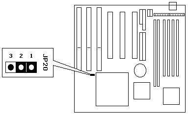
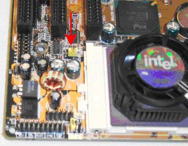
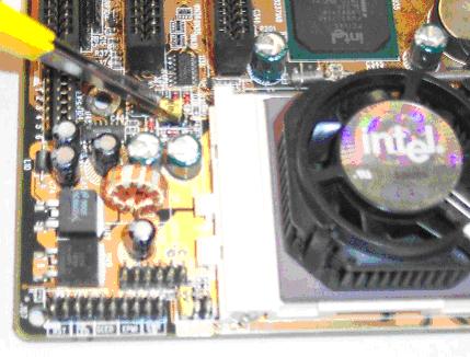
  25. The large extension of CMOS RAM that stores the PCI bus configurations is called:


  26. Write the DEBUG commands that will clear the CMOS on AT compatible systems:


  27. This DEBUG script does not actually clear the CMOS RAM settings what does it do?


  28. Because of the fact that this operation changes a value without changing the checksum of the values that must also be stored in the CMOS, the POST detects the error and automatically assumes that all values in CMOS are invalid and so it clears the CMOS RAM and prompts the user to enter the:


  29. Because the CMOS settings have been completely discarded by the POST program in the event of a CMOS checksum failure, once the user enters the BIOS Setup Utility what should be the very least action?


  30. Once all CMOS settings are thrown out due to the checksum failure, what will also be thrown out allowing access to the BIOS Setup Utility again?


  31. If the CMOS RAM has a BIOS Boot up password set can the DEBUG “script” be used? Explain. Explain what has to be done in order to clear the Boot Up password.


  32. List steps one and two of the PC boot sequence.


  33. If the boot sequence is set to “C, A, CDROM” what is the only condition that will allow the system to boot to the floppy?


  34. A warm boot is performed by:


  35. A cold boot is performed by either __________________ or ___________________.

  36. When performing a power cycle on the PC one should wait _______ seconds before turning it on again because:


  37. What BIOS'es are given control prior to the full POST of the motherboard BIOS? Give and example.


  38. The POST will only perform a total installed RAM check from a ___________ boot.

  39. What does the acronym POST mean and describe what it does.


  40. Describe what happens after a successful POST in the startup process.


  41. The BIOS Boot Strap Loader will load a sector from the boot disk into RAM by accessing what other BIOS software component?


  42. What standard BIOS software component does not execute during a normal startup?


  43. The BIOS 16-bit device drivers are custom designed to communicate with this particular system's:


  44. The BIOS 16-bit device drivers present a standard set of low level functions that an

    ______________________ _________________________ can use to access any PC's hardware allowing it to work on any PC.

  45. Programs can use direct BIOS function calls but it is far easier and more reliable to use the

    _______________________ _________________________ ______functions instead.

  46. One of the reasons that the operating system’s API functions are easier to use than the BIOS

    functions is because the operating system organizes programs and data into ________________

    with user-friendly ________________ within its file system.

  47. The built-in program that launches the operating system on the PC is called the:


  48. This program is part of the ___________________ stored on a read-only memory chip installed on the motherboard.

  49. The original type of memory chip that held the BIOS code was called a:


  50. The first program code to execute after a power on or reset of the system is the:


  51. This program code is the first of four main software components of the system’s:


  52. After a successful POST the POST program code will automatically pass control to this section of the BIOS:


  53. The BIOS Boot Strap Loader Code will attempt to read a boot sector from a ______________ drive or device. If this sector is successfully read into RAM and looks correct it will pass control of the CPU to it.

  54. Once the BIOS Boot Strap Loader passes control to a boot sector read from a bootable drive or device, the BIOS is no longer in direct control of the CPU but what part of it will still be available and be accessed throughout the computing session?


  55. What is the primary program code that will be accessing the BIOS 16-bit device drivers throughout the computing session?


  56. Applications on occasion access the BIOS 16-bit device driver functions but more often access the:


  57. One of the most important services that the operating system provides is a major organization of all information stored in the hard drive’s partitions called the:


  58. The reason that the operating system’s file system is such a valuable service is that it organizes all

    information stored on the drive including programs and data into ____________________ named files.

  59. An OS API function can be asked to open a data file by its user friendly file name which is far easier

    to remember than the tedious list of physical _________________ that it occupies on the surface of the drive.

  60. In order to track down the data file and read it from the physical sectors of the drive the operating

    system depends on the BIOS'es low level ________________________ and its standard function calls.

  61. On this BIOS how do you change a value in the Setup Utility once selected?


  62. On this BIOS how do you select a value in order to change it?


  63. Name four different settings that can be manually made in the Standard CMOS Settings screen:


  64. Name one setting that the system adjusts automatically and it can only be observed from the Standard CMOS Settings screen:


  65. List and describe three values that can be adjusted in the BIOS Features screen:


  66. List all possible boot sequence settings available on this BIOS:


  67. List three BIOS Setup Utility settings that could prevent the system from booting from a known good bootable floppy diskette:


  68. Describe one hardware level installation problem that could prevent the system from booting to a known good floppy drive even if it is configured properly in the BIOS


  69. Describe two reasons why a technician would need to clear the CMOS settings:


  70. Describe three methods hat can be used to clear the CMOS settings and which is the most prefered and which is the most prefered hardware method:


Copyright©2000-2007 Brian Robinson ALL RIGHTS RESERVED