CET1172C Lecture #11 - Using a Digital Multimeter
| Required Materials: IMPORTANT READ THIS CAREFULLY!
Do NOT spend a lot of money on these items. Please shop around and try to find an inexpensive DMM, and stripper/crimper with crimp set.
 Digital Multimeter (DMM) Digital Multimeter (DMM)
Also called Digital Voltmeter (DVM) or sometimes just called Multimeters or Voltmeters, but do not get an analog multimeter, these are the ones with the swinging needle instead of the digital display read out, they are NOT accurate enough and much more difficult to read. 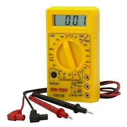 Wire stripper/crimper tool. Wire stripper/crimper tool.
Be sure to get the tool that can do both strip and crimp the connectors all in one, they are usually cheaper and often come in a set with the crimp connectors included. 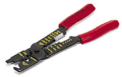 Wire terminal crimp connectors. Wire terminal crimp connectors.
Be sure to get a set that has the "blade" disconnect type male and female crimp connectors shown here.  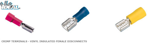 Internal drive power extension cable, or drive power "Y" cable. Internal drive power extension cable, or drive power "Y" cable.
These are available on the cabling peg hanger racks at any retailer that sells computers and parts. 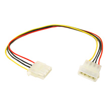 Objectives: The student should become familiar with: The basic measurements and units of electronics,The basic functions of a Digital Multimeter,The basic methods of testing PC power supplies,The basic methods of testing cables.Competency: The student will become familiar with the basic measuments and units of measure of electronic circuits including voltage, amperage, adn resistance. The student will become familiar with the basic functionality of a digital multimeter and be able to use it to measure the voltages provided by the PC power supply. The student will be able to recognize the basic industry standard power supply wires, their voltages and be able to test them. The student will understand how to use the digital multmeter to test a cable for continuity. |
-
Electricity was already defined in CET1171 as the movement of electrons. Furthermore it was explained that conductors, primarily but exclusively metals allow electrons to move through the loose outer shells of their crystalline structure, while nonconductors or insulators do not allow electrons to easily pass through them because this loose outer electron shell structure is absent.
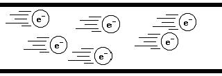
Electrons flowing through the metal core of a wire -
There are specific quantities that can be measured in any circuit. In fact the term circuit itself can now be defined.
Definition: Circuit - Continuous pathway throughwhich electrons can flow and do work.
-
The doing work part of the definition is important. If the electrons are allowed to flow completely unimpeded, then they will certainly do so, and they will move with such force that they will melt the wire and start a fire.
Definition: Short circuit - Electrons moving through a complete pathway unimpeded.
-
Short circuits blow fuses or trip circuit breakers which are designed specifically to detect them and cut the circuit path to prevent further damage such as the melting of insulation and even causing the insulation to catch fire. During the experiments on the pwoer supply described below it is imperative that you avoid allowing any power wire to come into direct contact with ground, which is the casing of the power supply or the chassis of the PC. You are not shorting just a +5VDC line, the short goes through the power supply circuitry to the wall outlet which because the electrons are unimpeded can deliver over 30A before tripping the circuit breaker. This is capable of causing a large enough spark and heat that you can be seriously injured.
-
There are three specific quantities within a circuit that can be measured. The first is the amount of electrons passing a particular point in a circuit pre unit time. Imagine standing on the side of a road and counting the number of cars that pass by you per minute. Let's say that it is 10 cars per minute. If we defined a unit say a "kerplunk" as 1 car/minute, you could then say that the road is experiencing 10 "Kerplunks" The same is true for electron flow through a wire. The unit of measure is called Amperes or Amps (symbol "A") and expresses the Amperage of the circuit at that point.
The number of electrons passing a point per unit of time: Amps -
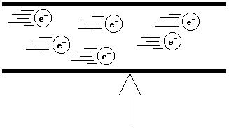
The amount of potential or force that is pulling on the moving electrons at that point is measured as voltage and the unit of measure is the Volt (Symbol "V"). The voltage or force that is pulling the electrons through a circuit is generally provided by the power source which could be either a battery or an electrical generator.
The electrons are pulled by a greater force: Volts -
The amount of electrons passing through the circuit is determined by how many electrons the circuit needs in order to work and whether the power source can provide them and finally whether the wires leading through the circuit and the components can handle them all without overheating and failing. This "supplied if needed" behavior is why the amperage is often referred to as the amount of amperage that the circuit "draws" implying that if it needs the electrons and the power source has them the circuit will draw them out of the power supply.
-
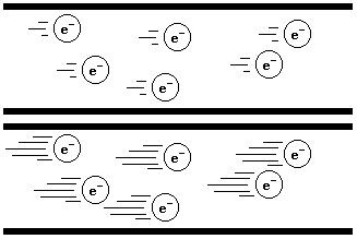
The third major measurement in electricity is resistance. This is measured in Ohms, named after a German pioneer in electricity and the symbol for these units is the capital Greek letter omega: Ω. An Ohm is a fairly small unit of resistance, while a Volt might be considered a rather convenient unit and the 1 Amp is actually rather large. Most digital electronic equipment operates on a few volts, but draws milliamps (Symbol "mA") or thousandths of an amp, and circuits use resistors to create "bias" that forces electrons to flow at a certain rate through the circuit that are thousands of Ohms or "kilohms" (Symbol "KΩ").
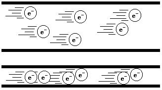
The electrons have greater difficulty passing through the thin wire: resistance -
Resistance is exactly what it sounds like: resistance to the free flow of the electrons through the material that has the resistance. Even silver wire, the best conductor of electricity, has some resistance to the free flow of electrons through it. This is because there is a physical limit to how many electrons can be pushed through a narrow wire in much the same way that there is a limit to how much water can flow through a narrow water pipe. The measure here is Amperes, the number of electrons passing a point in the wire per second. Obviously an infinite number of gallons per hours cannot pass through a water pipe and the narrower the pipe is, the slower the rate of water expressed in gallons per hour that it can deliver. A 4 inch pipe must be able to pump a larger amount of water in gallons per hour than a drinking straw. It does not matter how strong the pipes are or how strong the pumps are, there is a physical limit to how many water molecules fit into the square area of the cross section of the pipe at any given moment. The same is true of electrons being pumped through a wire by the voltage potential difference across the poles of a battery. While in water it would be measured as pressure until the pipe breaks, this limitation to electrical flow is measured as resistance, which converts potential energy loss into heat until the wire melts.
-
The student will learn how to measure these three values on a standalone PC power supply which will be bench tested. Bench testing means that the item to be tested is to be tested under a controlled condition and not in its native or normal circumstances. This will certainly be true for the power supplies, since they will be outside of a PC case. Note: under no circumstances should you plug a power supply into an outlet if its outer housing is loose or missing.
-
The PC power supply is certainly one of the most enigmatic of all problem components. Symptoms usually include random sudden reboots, or random sudden lockups, or failure to turn on the first time, but starts up fine on the second attempt, any combination of these, or other strange randomly occuring behavior. Power supplies can certainly go bad after time, but they can also be underpowered for the total collection of components that they need to provide power to within the system.
-
The power rating of the power supply is given in the units called Watts (symbol "W") which is a unit of work and is found by multiplying the voltage that the device is using by the amperage that it is consuming or drawing from the power source. In general small name brand systems will probably have the smallest power supply that can possibly provide the necessary power to the system. Adding even a single drive could exceed their capabilities and this should be kept in mind when upgrading name brand systems. Modern generic custom made PC's should be set up with a minimum 400W power supply, although power supplies over 500W are just as inexpensive at times and would be preferred.
-
The PC technician should be able to bench test the power supply properly and should have a standard AT, ATX 1.0 and ATX 2.0 spare power supplies handy.
-
The AT motherboard power connector pinout:
P8 1 Power_Good signal to the motherboard for power-on/reset events. 2 +5VDC But the motherboard does not usually use it. 3 +12VDC. 4 -12VDC. 5 Ground. 6 Ground.
P9 1 Ground. 1 Ground. 3 -5VDC. 4 +5VDC. 5 +5VDC. 6 +5VDC. -
The ATX motherboard power connector pinouts:
+3.3VDC 1 11 Dual AWG22 wires: +3.3VDC and +3.3V sense +3.3VDC 2 12 -12VDC Ground 3 13 Ground +5VDC 4 14 Power On Ground 5 15 Ground +5VDC 6 16 Ground Ground 7 17 Ground Power_Good 8 18 -5VDC +5VDC Standby 9 19 +5VDC +12VDC 10 20 +5VDC Additional 4 pins on the ATX 2.0 connector (note: pins #11 to 20 above become #13 to 22):
+12VDC 11 23 +5VDC +3.3VDC 12 24 Ground -
Therefore it can be seen that Pins #1, #2, and #11 supply the +3.3V needed by the new (at the time) lower voltage Pentium processors. Pin #11 can have an additional wire which is for the motherboard circuitry to sense the voltage on the line. Pins#4, #6, #19, and #20 provide +5VDC to the chips on the motherboard (and expansion cards installed in expansion slots) that run on +5VDC. Pins #3, #5, #7, #13, #15, #16, and #17 provide common ground for all circuits in the system. (Note: all pin numbers here are the correct pin numbers for the 20-pin ATX 1.0 power supply-to-motherboard connector)
-
Pin #8 is used by the power supply to signal the motherboard that it is providing good stable power to it. When it has a voltage on it (as opposed to zero) it is indicating that all +3.3V and +5V lines are stable and reliable, this is when the chipset will allow the CPU to begin operating on a power on or reset.
-
Pin #9 is the +5VDC StandBy voltage. This remains available when the system goes into "Energy Star - Green PC" standby mode so that circuitry can continue to function and be able to bring out of standby mode. Devices that require power after the power supply has turned off can tap this line for power as well. While the power supply is turned off, "Wake-on-LAN" or "Wake-on-Ring" or "Keyboard signal power on" ACPI compliant devices can run on the power provided by this line and be able to start up the system.
-
Pin #10 provides +12VDC which is used by drive motors even though most modern drives use +5VDC motors. Most fans still tap the +12VDC for power, however. Fans usually have a smaller side tap three wire connector to the motherboard. This provides them with the positive voltage and ground that they need to operate, and the third line can be accessed by motherboard circuitry to monitor the RPM of the fan. This is made available through the BIOS ACPI complaint interface to any software designed to access it. This is the basis for active hardware monitoring software.
-
Pin #12 is the -12VDC which is needed by some circuits including the serial port UART.
-
Pin #14 is the PS_ON signal line The power supply keeps a signal on this line. When the motherboard pulls it low by shunting it to ground, the power supply will then turn on. This is the very function that makes the power supply a peripheral component under the control of a motherboard circuit which can be controlled by software in that it is a small peripheral component with an I/O address and can be driven by a driver program.
-
Pin #18 provides the -5VDC again for any circuit that requires the opposite polarity of +5VDC in order to function.
-
Modern standard AT and ATX power supplies are equipped with a number of standard drive power connectors that can be used to power the drives installed on the system. Unused power connectors can be left unattached to anything and they will have no ill effects on the power supply. However, it is a very good idea to use tie wraps to bundle power cables both used and unused within the case to keep the interior neat and all components easily visible. Do not pull tie wraps too tightly and they should be left very loose when wrapping data ribbon cables. The better plan for data ribbon cables is to purchase round data cables and then tie wrap them to the case somewhere if needed.
-
AT power supplies began incorporating automatic switching technology. The power supply will automatically switch itself off internally if there is insufficient power drawn from it when it is turned on. This is done because the internal circuitry of the power supply will burn itself out if it is generating a certain amount of power and there are no circuits using it. This means that in order to "bench test" a power supply you should attach at least one HDD to one of the standard power supply cables. Obviously this is a bench test outside of the case so the HDD does not need to have a data cable attached to it as well. The HDD is only there to draw the power to spin up the spindle and begin calibrating the stepper motors which will consume enough power to keep the power supply on and also keep it from being damaged by running it with no current drawn from it. This autoswitching was standardized in the ATX power supply as well, so bench testing the ATX power supply should also be done with an HDD attached to it.
Here are the standard drive power connectors found in most power supplies and the voltages that the wires deliver to the device:
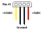
Standard Molex type drive power connector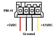
Standard Floppy drive power connector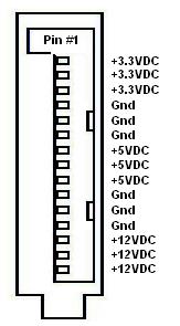
Standard SATA HDD power connector -
But there is another problem in bench testing the ATX power supply besides making sure that the power supply has a device attached that will provide sufficient current draw; it has no physical power switch to turn it on. In order to bench test the ATX power supply, a logical signal must be sent to the power supply normally from the motherboard, but it can be sent for a bench test as well. Simply shunt the PS_ON line (Pin#14 in the 20-pin connector or #16 in the 24-pin connector) usually the only green wire, to ground using any stiff wire.
Bench testing an ATX power supply: Shunt PS_ON to Ground -
As of the ATX 2.0 Standard specification the voltage tolerances for all output lines of hte power supply are:
Line Tolerance +5VDC (RED) ±5% -5VDC (white) ±10% +12VDC (YELLOW) ±5% -12VDC (blue) ±10% +3.3VDC (ORANGE) ±5% +5VDC-Standby (purple) ±5% -
Setup a power supply for bench testing, attach the any hard drive to any standard drive power connector. Plug the power supply to a known well wired and grounded outlet. In the case of an AT, turn it off if it is already on. In the case of an ATX, shunt the PS_ON line to any ground in the power supply-to-motherboard connector. This is done by inserting a stiff wire such as a modified bare metal paper clip into the green wire's post and any black wire's post in the connector. Observe if the power supply fan begins to spin, if it does, then it is on.
-
Set up the DMM to read Voltage DC in the roughly 20V range. Attach the probes to the correct posts on the DMM. Press the red probe into any standard drive power connector's red wire post, and then press the black probe into the either black wire's post in the same connector. Record the voltage displayed on the DMM. Remove the red probe and insert it into the yellow wire's post. Record the voltage displayed on the DMM. Repeat the procedure testing both power wires to another standard drive power connector on a different circuit coming out of the power supply. Be sure to record the voltages.
-
Test the white and blue wires in the power supply-to-motherboard connectors and record the voltages. In the case of an ATX power supply test the orange wires (either Pin #1 or #2 ONLY) and record the voltages. Try to test the purple wire also.
-
Shut down the power supply and begin to create an amperage testing "rig". This is done by cutting the red and yellow wires (only) at the exact midway point between the female and the male standard hard drive power molex connectors of the standard drive power extension cable (or drive power "Y" cable).
-
Then strip roughly 1/8" of insulation off of each cut wire tip.
-
Now crimp a male disconnect crimp to one of the cut red wire ends and a female to the other. Repeat the procedure crimping a male disconnect crimp to one of the cut yellow wire tips, and a female to the other. Connect the red wire male crimp to the red wire female crimp and connect the yellow wire male crimp to the yellow wire female crimp.
-
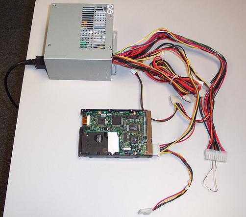
Be sure that the power supply is OFF before proceeding. Attach the "rig" to any standard drive power molex connector of the power supply. Then attach the hard drive to the other end of the "rig" so that in order for power to reach the drive it must pass through the crimp connections. Be certain that the "rig" will not be jostled and that the base metal crimp connections cannot come into contact with ground. Place a rubber mousepad upside down on a level surface and place the "rig" connections on top of this.
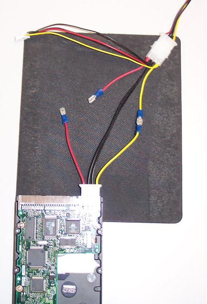
Amp testing "rig" in place ready to try -
Disconnect the red wire crimps and set the DMM to read the roughly 2A (Amps) range. Press the red probe against the red wire crimp that leads directly to the power supply, and press the black probe against the red wire crimp that leads to the hard drive. Be absolutely certain that the probes are pressed firmly and securely against the crimps.
-
Have someone else turn on the power supply for you and if necessary have someone else read the DMM. Record the range of values, the hard drive does not pull a constant amount of power and most modern hard drives have sensitive circuitry that can detect that the power arriving through the power supply connector is not good. In that case they will not initialize the spindle motor to avoid a head crash. Nevertheless, the circuit board will use some small amount of power which can be recorded. Note: the DMM will likely need to be reset to a lower range such as 200mA in order to detect this. Note: turn off the power supply, then adjust the DMM setting, then turn the power supply back on.
-
Set the DMM to read the lowest resistance range possible, such as 1MegΩ and test the ends of a (completely unplugged!) standard AC power cable. Place either probe into the computer side center hole and then touch the other probe to the outlet side center prong. Resistance should approach zero. If it stays "infinite" then the cable is bad and should be discarded (except for those kept for the purposes of this class, of course) Then test each of the other lines for continuity as well.
-
What is an electron?
-
What is the definition of electricity?
-
What is the definition of a circuit?
-
What is the definition of a short circuit? Why should these always be avoided?
-
What three quantities can be measured in any circuit?
-
What is the unit of measure corresponding to the number of electrons that pass a particular point within a circuit per unit of time? Is this a convenient unit of measure for digital electronics? If not what modified form of the unit is used commonly instead?
-
What is the unit of measure corresponding to the force acting on the electrons at a particular point within the circuit? Is this a convenient unit of measure for digital electronics?
-
What is the unit of measure corresponding to the force against the flow of electrons through a particular path or component of the circuit? Is this a convenient unit of measure for digital electronics? If not then what modified form of the unit is used commonly instead?
-
When testing voltage it is best to set the DMM to a range lower, higher or the same as the expected voltage in the wire?
-
When using the DMM to test amps it is best to set the range lower, higher or the same as the expected amperage in the location?
-
What units must the DMM be set to measure in order to test a cable for continuity?
-
What feature of the modern PC power supply makes it necessary to attach a hard drive to any connector in order to bench test them?
-
Why do the power supplies have the feature mentioned in the question above?
-
Some DMM's have different locations for the probes depending on what quantity is being measured. Given these connectors where does the red probe attach in order to measure connectivity in a wire?
  A   V    COM    Ω
 (O) (O)   (O)   (O)
-
You would attach the black probe to which connector in the preceding question?
-
Why was it important to place the amp testing "rig" you made in this experiment securely on top of a rubber mouse pad?
-
ATX power supplies do not have a physical throw on/off switch, so how can they be bench tested anyway?
-
Use the following lines to record your voltage data from at least two separate standard molex type drive power connectors of the power supply. Calculate whether they are within the ATX 2.0 specification tolerances.
-
Use the following lines to record your voltage data from the required lines of the power supply-to-motherboard connectors. Calculate whether they are within the ATX 2.0 specification tolerances.
-
Most hard disk drives will not actually activate their spindle and stepper motors during the amp testing experiment we performed. Why?
-
Is the Pin #1 line of the standard floppy drive power connector the same as Pin #1 of the standard molex drive power connector? What voltages do they carry?
-
Based on your observations of the ATX Auxillary "2x2" connector, what voltages does it provide to the motherboard?
-
What additional voltage lines does the ATX 2.0 power supply provide to the motherboard that the ATX 1.0 power supply does not? What are their pin numbers?
-
What would be considered the minimum safe wattage for the power supply of a custom built modern PC?
-
What two pins of any ATX power supply can be tested for proper +3.3VDC?
-
What is the function of the PS_ON connection in the ATX power supply-to-motherboard connector? What is the standard color for this wire?
-
What is the function of the POWER_GOOD connection in the ATX power supply-to-motherboard connector? What is the standard color for this wire?
-
What is the function of the +5VDC Standby connection in the ATX power supply-to-motherboard connector? What is the standard color for this wire?
-
When testing amperage the red probe must be connected to the point leading to the power source or the device? Which point should the black probe be connected to?
-
When testing voltage in a standard molex type drive power connector, the red probe is inserted into the red wire's post and the black probe is pressed against the bare metal of the case. Will this work? Explain.
-
What standard peripheral needs to tap a negative voltage line?
-
How many lines of the standard 20-pin connector provide +3.3VDC to the motherboard? How many in an ATX 2.0 connector?
-
How many lines of the standard 20-pin connector provide +5VDC to the motherboard? How many in an ATX 2.0 connector?
-
How many lines of the standard 20-pin connector provide +12VDC to the motherboard? How many in an ATX 2.0 connector?
-
How many lines of the standard 20-pin connector provide ground to the motherboard? How many in an ATX 2.0 connector?
-
You are inspecting the interior of a proprietary system and notice a 4-pin keyed connector similar to an ATX auxillary connector attached to the motherboard. It has one yellow, one blue and two black wires. What is the most likely peripheral that this would be providing power to?
-
Your customer would like to add a second "data" hard drive to his name brand PC. What complication could the power supply introduce to this scenario possibly even preventing the upgrade?
-
You determine that a PC is drawing 4.9A from the wall outlet. What is the wattage that this power supply is running at? The sticker on this power supply reads "Power: 550W" can this power supply continue under these conditions? If not, what can you do?
-
What voltage does the standard SATA drive power connector provide to the drive that the classic standard drive molex type connectors did not?
-
What is the most common device left in modern systems that still uses +12VDC?
-
A case fan has two different connectors that can be used, a standard side tap three wire connector and an adapter for this to attach to a standard molex type drive connector. If you use the standard molex type connector adapter to power this fan what feature will be lost?
-
Certain ACPI compliant devices can remain active even when the system is completely turned off, how do they receive the power to function? What unique function are they capable of concerning the power supply?
-
Proper ESD protocol for an ATX based system involves unplugging the power supply then disconnecting the power supply-to-motherboard connector, then plugging the power supply back into a properly wired and grounded outlet, then proceeding to service the system. Why are these extra steps necessary?
-
Assuming that a system averages 2A of draw from a standard electrical outlet while not in use, but in normal operating mode and 1A while in standby, how much money would be saved by standby mode if the system were left on all month and the power company charges $1 per KW/hr?
Copyright©2000-2007 Brian Robinson ALL RIGHTS RESERVED