MSM2 Lecture #1 - IRQ's
Materials: Working complete PCBootable diskette, "New Boot A Ver 2" Working complete PCBootable diskette, "New Boot A Ver 2"Objectives: Describe the physical nature of IRQ's,Describe the PIC's and their physical wiring,Describe the Interrupt process,List the standard IRQ device assignments,Use various diagnostic tools to determine actual IRQ assignments, andLearn how to resolve IRQ conflicts.Competency: The student will become familiar with the system resource IRQs and be able to examine and change device IRQ settings in BIOS, Windows, and the physical device hardware or configuration software. |
-
The instructor will issue each student a complete system unit, monitor, keyboard, and mouse. Boot the PC into Windows 98 normally. Open the Device Manager.
-
Now right click on the My Computer Icon and then click properties. A new window appears that provides access to the system resources, click on the Device Manager tab. This utility provides access to and status for all of the individual hardware components of the computer. Normally it opens by default to display the system components listed by type. If all detected devices are functioning properly then all type categories will be closed. If any particular device is not functioning properly then the category will be open and the device with the problem will be visible with one of two possible overley icons next to it. The yellow (!) usually indicates a functional device with a software driver problem while the red (x) usually indicates a hardware level malfunction. These indicators are Device Manager's best guess and cannot be fully trusted. Standard resource assignment lists can be displayed by Device Manager as follows. Right click on the Computer icon at the top of the device list This popup menu appears:
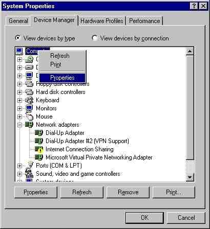
Click the Properties choice of the this menu and a new window appears with the system resources listed in it. By default this window will list the IRQs first and looks like this:
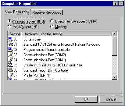
IRQs are the least understood resource and conflicts can be very difficult to diagnose and deal with. Because unlike the I/O addresses, IRQs are very limited in number so conflicts arise often. Write down all the IRQ assignments displayed in this window.
-
Close Device Manager and open MSINFO32. In this class there will be a series of items that have to be clicked in order to perform a particular activity. These will be presented as follows. To run MSINFO32: Start > Run > "MSINFO32" > OK. This means to click the Start button which opens a menu. On this menu there is a choice called Run. Now click this. This opens the Run dialog box. Now manually type in the the quoted string into the text box. Now click the OK button. When a right click is needed this will be indicated as "Rt. Click". When a checkbox must be checked this is indicated as "Check ..." to uncheck it will be indicated as "Uncheck ..." In Radio button choice sets the one to select will be indicated by name. Now that MSINFO32 is open, click the [+] next to Hardware and then click on IRQs. Compare this list to the one you got from device manager. Any discrepancy could eventually lead to a problem with any of the devices involved in the discrepancy.
-
Now click on Conflicts/Sharing. Write these down in the list at the back of this lab module. It should be noted that IRQs cannot actually be shared. But the PCI bus is capable of fooling the devices into using different physical IRQ lines. Heavy activity on "shared" IRQs can bog down the performance of the system.
-
Close MSINFO32. Insert New Boot A in the diskette drive and properly restart the system: Start > Shutdown > Restart > OK. If necessary press [Delete] and enter the BIOS during the reboot and change the boot sequence to Floppy Diskette first, save this change and exit. At the boot menu of New Boot A select choice 2 "Full Deploy w/o CDROM Support" When the deployment is complete the system will display the K: drive prompt. Run the Microsoft Diagnostic utility by typing msd then [Enter]. Once MSD is open check the IRQ list by pressing the [Q] key. Write down the IRQ list and note any differences. These are due to differences in the Sharing strategy of the PCI controller/arbitrator in real mode versus protected mode.
-
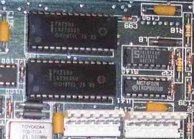
Interrupt Requests are actual wires or printed circuit board lines that carry the device's signal to the PIC - Programmable Interrupt Controller. The original IBM PC had a single Intel 8259 PIC which was an 8-bit chip supporting 8 IRQ lines (0 through 7). The two 8259 PIC's on an original AT generation IBM motherboard:
-
If a device needs to get the CPU's attention it uses its assigned IRQ to signal the processor. Some reasons that the devices need to signal the CPU are:
- to indicate the presence of data ready for the CPU to pickup
- to respond to a device ready query from the CPU
- to indicate an error has occurred
- any other device status or query responses
The problem with peripheral devices is that their needs often reflect real world activity which means that they are not in synchronization with the system clock. As a result, two devices could need the processor at exactly the same moment. Intel engineers decided very early in the design process to export this problem of IRQ arbitration to another chip (hence the PIC) to keep the design of the processor concise. Remember that the CPU is expensive and high speed, and responding to the keyboard (your finger strokes) does not have to be handled by this expensive, high speed circuitry.
The PIC's handle this process and due to the cascade here are the standard PC IRQ assignments in order of priority:IRQ Number Standard Device 0 System Timer 1 Keyboard 2 Cascade to IRQ9 8 Real Time Clock 9 Available 10 Available 11 Available (preferred by SCSI controllers) 12 Available, but assigned to PS/2 mouse if present 13 FPU 14 Primary ATA channel 15 Secondary ATA channel 3 COM2 or COM4 4 COM1 or COM3 5 LPT2 (but usually Sound Card) 6 Floppy Disk Controller 7 LPT1
-
When IBM redesigned the motherboard for the IBM AT they knew that 8 IRQs was too limited and so wired in the second Programmable Interrupt Controller. They gave it IRQ2 of the original PIC which had once been an available IRQ on the ISA bus. This nests all of the slave PICs IRQs into a priority level between IRQ1 and IRQ3. Furthermore, that old IRQ2 line from the ISA bus slots had to be handled so that it would not conflict with the slave PIC and its 8 other devices. A rough wiring diagram of the PIC's in the AT motherboard:
-
The old IRQ2 line was wired in to the new slave PICs IRQ9 line. The problem is that the device that fires the IRQ thinking that it is IRQ2 will have a problem when the processor executes the software interrupt for handling IRQ9...it is the wrong handler and the system could crash at worst, or the IRQ2 device will not work at best. To solve this problem, the IRQ9 interrupt code calls the IRQ2 interrupt handler code.
-
Reboot and at the boot menu choose Command Prompt Only and at the DOS prompt enter these commands:
C:\>debug
-d 0:0 ff
-
What we are looking at here in the Interrupt Vector Table. Since the IBM PC is based on the Intel x86 family of processors, and since these in turn are interrupt driven processors, and since they are general purpose computers, the engineers at Intel had to find a way to allow their interrupt driven chips to be able to have a completely flexible addressing system for responding to all of these peripheral device interrupts. Since it would be entirely unknown how much RAM any particular system would be equipped with, the chip was designed to reset to the address at FFFF:0000 near the top of memory which would reside on the EEPROM anyway. This left the absolute bottom of memory at 0000:0000 available and always present on any system no matter how little RAM it would have. When the chip executes an interrupt instruction it multiplies the interrupt number by 4 (each interrupt vector in the table is four bytes long) and then reads the address 0000:(INTnum) x 4. It reads those four bytes into the Code Segment pointer register (16 bits = 2 bytes) and the Instruction Pointer Register (16 bits = 2 bytes). The next instruction will be fetched from the address in RAM that was stored in the Interrupt vector. Example, INT 1 => read the four bytes starting at 0000:(INTnum = 1) x 4 => 0000:0004. Two bytes go into the CS = FE00 and two bytes go into the IP = 0400. Now the CS:IP = FE00:0400. This is where the interrupt handler code would reside on the EEPROM. At the end of the interrupt the chip executes an IRET (Interrupt RETurn) instruction in which the original CS:IP (that was "pushed" onto the stack in memory) is now "popped" back off of the stack and into the CS:IP. Now the chip proceeds with what it had been doing. Read this again.
-
You only need one more piece of information in order to use this IVT to find the "Cascade 2=>9". How are the hardware IRQs mapped into software Interrupts? The PICs are each given a base interrupt number (that's why they are called "Programmable") The master's base interrupt number is 8. So when IRQ0 line is activated, the PIC fires the INTR (INTerrupt Request) line into the CPU. When the CPU is done with its current instruction and decides that it is safe to be interrupted, it will save its current registers to the stack and then fire the INTA (INTerrupt Acknowledge) line. The master PIC then places the interrupt number onto the data bus lines D0 - D7 which the CPU is monitoring. When the CPU has the number it fires the INTA again and the PIC resets itself ("my IRQ has been taken care of so I can relax" says the PIC, unless two IRQs fired at the same time in which case the PIC would now raise the INTR line again. The CPU will ignore that until it is done with the interrupt code. In this case the PIC put the number 8 on the data bus. Now the CPU multiplies that by four and fetches the four bytes located at 0000:0032 into the CS and IP effectively jumping to that location and executing the hardware specific code for handling the device. This is why the motherboard manufacturers embed the code for reading and writing to the hardware devices built in to the motherboard in the BIOS and this is how the devices themselves can initiate the execution of the handlers to handle data without programs or you having to help. The slave's base interrupt number is 70h. It was chosen because no one had gone this high into the interrupt numbers. BIOS is generally all the numbers under 20h and DOS uses 20h to about 33h.
-
So IRQ8 would be INT 70h and IRQ9 would be INT 71h. Now 71h x 4 = 1C4h. So dump 0:1C0 on screen:
C:\>debug
-d 0000:01C4 L 4 0000:01C0 F3 EC 00 F0 .... -_ -
The x86 CPUs are called "little endian" processors because of the way they store data in RAM. When the CPU stores a 16 bit value like ABCDh at location 0100h they will land there with 0100h => CDh and 0101h => ABh, the bytes reversed. Further, the value at 01C4h is a doubleword or four byte value. So each of the words is also reversed. So if we store 01234567h the CPU will reverse the words: 4567 0123 then the bytes in the words: 67 45 23 01. This is how the dword 01234567h will appear in RAM. Armed with this information the byte series F3 EC 00 F0 must have the bytes swapped: EC F3 F0 00, then the words swapped: F0 00 EC F3. Now we have the CS:IP that the CPU jumps to in order to execute IRQ9 = F000:ECF3h. If we unassemble the machine language instructions located there we can see what it is that the CPU will do in response to IRQ9:
-u f000:ecf3
F000:ECF3 50            PUSH    AX     <-  SAVE CONTENTS OF REGISTER TO STACK
F000:ECF4 B020          MOV     AL,20  <-  PLACE THIS VALUE IN AL REGISTER
F000:ECF6 E6A0          OUT     A0,AL  <-  WRITE VALUE TO PORT A0 = SLAVE PIC
F000:ECF8 58            POP     AX     <-  RESTORE AX REGISTER
F000:ECF9 CD0A          INT     0A     <-  EXECUTE INTERRUPT Ah
F000:ECFB CF            IRET           <-  INTERRUPT RETURN
F000:ECFC 64            DB      64     <-  HERE DOWN IS UNRELATED CODE...
F000:ECFD 20536F        AND     [BP+DI+6F],DL
F000:ED00 50            PUSH    AX
F000:ED01 1E            PUSH    DS
-
The actual bytes of the instructions are highlighted in yellow. As you can see, the assembly language translations of them are much easier to understand. We see that the CPU saves the AX register to the stack because it is about to use it. In the next instruction it sets the AL (lower byte of the 16 bit AX register) equal to 20h. In the next instruction it writes the 20h in AL out to I/O address A0h which is located on the slave PIC. It then restores the AX register. Then it calls interrupt Ah which will contain the IRQ2 handler code. Where 8 is the master PICs number base, then IRQ0 = INT 8h, IRQ1 = INT 9h, and IRQ2 = INT Ah. This is how IRQ2 => 9 cascade is accomplished. IRQ2 wire goes to IRQ9 wire of the slave PIC. When the interrupt (71h) is executed it simply calls the interrupt code for IRQ2. Note that when the slave PIC fires its INTR line into the master PICs IRQ2 line the master will not respond to the CPU's INTA signal which would cause it to write on the D0-D7 lines the value Ah at the same time the slave PIC will be trying to write its INT number on to the D0-D7 lines. The master will only reset on an INTA in response to IRQ2 so that the slave PIC can put whatever number it has to onto the D0-D7 lines.
-
Exit DEBUG and reboot. As you do enter the BIOS Setup. In BIOS enter the menu titled PnP/PCI Configuration. Record all settings on the worksheet at the end of this module. The PnP OS installed - Enabled/Disabled entry has a profound influence on PCI cards drivers. It should be set to Disabled for any OS that does not support Plug-N-Play which for Microsoft are: DOS and Windows NT 4.0 Workstation or Server. This setting should NEVER be changed on a client's system even if it is set incorrectly because it will change system resources allocation to devices including IRQs, DMAs and possibly even I/O ports. When set to disabled the BIOS will initialize and assign all system resources to devices before the OS loads and takes control of the system; during the POST. When enabled the BIOS will not necessarily assign system resources and allow the OS to assign them after it loads into memory. By changing this setting you will cause a change in the assignment of system resources to at least one and maybe even all devices, this could cause the OS to crash while loading, and certainly cause it to "detect new devices" and begin extracting new DLLs and VxDs which can be catastrophic to the OS, especially if you go and switch it back again.
-
Reset Configuration Data has to deal with the CMOS settings for the PCI bus arbiter. Just like the old AT CMOS settings held the Boot Sequence, amount of RAM, number and geometry of FDDs, etc, the PCI bus controller must detect PCI devices and then negotiate resources with each device then store this information in CMOS. These settings are referred to as the Extended System Configuration Data or ESCD. Where the AT CMOS held 64 bytes then was later expanded to 128 bytes then 256 bytes. However, the ESCD CMOS can be megabytes in size. If you install a device that causes a crash, then remove it and the system does NOT report that the ESCD has been updated and the system continues to crash, then enter the BIOS and tell it to reset the configuration data and reboot. This has the effect of clearing the PCI CMOS. It will automatically redetect all of the PCI devices and configure them again anyway. Be aware that this can change their settings!
-
Resources controlled by Auto/Manual. Under normal circumstances when the PnP OS is enabled above then this should be set to Auto. When PnP OS is set to disabled this should be set to manual. Set it to manual to enable the IRQ Resources entry. Then open the Manual assignment list. Put a check next to each one listed here in the standard assignment list at the end of this module. Usually you have two choices PnP/PCI or ISA/Legacy. If the IRQ is PnP/PCI then the PCI bus controller has access to that IRQ and can give it to any of its devices. When the entry is ISA/Legacy the PCI bus controller has no access to that IRQ. This should be done for any legacy device (all ISA cards are legacy) and any PCI card that is not functioning properly. Now go back to the main menu and then enter the Power management menu.
-
You should never modify these settings on a clients PC after the OS has been installed. This will have the most dramatic effect on how the PnP OS "sees" the motherboard. By deactivating or activating ACPI, Windows upon reboot might have to reinstall drivers for every single device in the motherboard including the system resource managers (PICs, DMA controllers, etc). During this process it will load new drivers and modify the registry. The potential for permanently damaging the Windows installation is quite high.
-
Now disable ACPI. Save and Exit. Restart Windows 98 in Normal mode. Windows will proceed to reinstall drivers for the motherboard devices because they look completely different when not under the Plug-N-Play ACPI subsystem's control. Low level system software that requires direct access to the hardware like antivirus packages, system maintenance utilities, CD-ROM burner software, etc can be dramatically affected by these changes.
-
When Windows is back to the desktop open Device Manager. Now open [+] in front of the System Devices. This is all of the devices built in to the motherboard. Right click on the PCI Bus and select properties. The window that appears should report that the device is working properly in the General tab. (If it weren't it would be flagged with a yellow "!" in the main Device Manager window). Now click on the Settings tab. Device enumeration is the order in which devices will be initialized. If you add a new PCI device and it is not working, try changing this to BIOS rather than hardware. This puts faith in the motherboard PCI bus controller to be able to complete a successful POST and therefore tell Windows in what order that POST completed successfully as opposed to simply initializing the cards in the slots in order. In the PCI bus each slot is numbered and the order in which the cards are installed is very relevant and can affect whether a card will function. Again, making a change like this can have serious consequences on reallocation of motherboard resources and Windows should be backed up before such changes are made.
-
Now click on the IRQ steering tab. If the "Use IRQ steering" checkbox is clear then PCI devices could have plenty of problems. It should be noted that if Windows did not enable it, then there is a problem with driver support for the PCI bus controller/BIOS of this motherboard. You should check the documentation for a possible driver that needs to be installed at this point. The four other checkboxes allow enabling or disabling of the four PCI resource assignment control tables. List these on the worksheet and make a note of which ones are enabled on your system and which ones are not enabled.
-
These tables are searched in the priority in which they are listed. Note that this search order cannot be changed. You can only activate or deactivate the usage of a table. This can be done to force Windows to use another table if a Plug-n-Play device is failing to install the drivers properly. The status box below indicates which one was used to determine system resource allocation. Deactivating the ACPI table checkbox here would have had the same effect as deactivating ACPI in BIOS if Windows indicates that it was the table used to determine device resource allocation. If a PCI expansion card refuses to function despite following the manufacturer's instructions for installing the device and its drivers, you can select another PCI resource table for Windows to use. Windows should definitely be backed up before this is done.
-
Reboot and enter BIOS Setup. Open the Integrated Peripherals menu make sure that the integrated sound card for the motherboard is disabled. Windows 98 does not have built in drivers for this particular cound card and it is also an integrated PCI (therefore Plug-N-Play) device, Windows 98 will automatically detect the device on each boot up and launch the Add New Hardware Wizard. Since the drivers are not available the user might cancel the installation attempt, after which the user might be compelled to cancel it on every subsequent reboot as well. To avoid this hassle this motherboard allows the device to be disabled in the BIOS which is effectively the same as removing it from the system. It will not activate and it will not respond to PCI bus scans which means Windows 98 will not detect it and therefore will not launch the Add New Hardware Wizard. Since Windows does not need this device, disable it now then Save and Exit.
-
It is important to understand that IRQ's cannot be shared under any circumstance. Despite this Windows has referred to IRQ's as "Conflicts/Sharing" in MSINFO32. But the reference to "IRQ Steering" is much closer to the truth about what is actually happening. First, the classic AT IRQ lines do not pass beyond the PCI bus controller. PCI devices have their own interrupts for contacting the PCI bus controller but they are not the AT IRQ's and behave very differently.
-
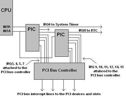
So how do PCI devices activate an IRQ that will in turn interrupt the currently executing program and start up their driver code? The classic AT IRQ lines do reach the PCI bus controller itself. The PCI bus driver has positioned itself in RAM and placed its own address to be the driver address in the IVT for every IRQ that PCI devices might use. When a PCI device signals a PCI interrupt across the PCI bus to the PCI controller, it then keeps a number in one of its own physical registers that can be accessed by its own driver. It then fires any available IRQ line which reaches the PIC, which activates the classic interrupt operation with the CPU. When the CPU reaches the IVT and executes the jump to the driver, it is the PCI bus controller's driver that executes. Here is the conceptual wiring diagram. Note that the IRQ attachments to the PCI bus controller are in addition to their attachments to any legacy devices on the motherboard like a PS/2 mouse. The BIOS settings tell the motherboard chipset whether to allow the PS/2 controller to use the line or the PCI bus controller:
-
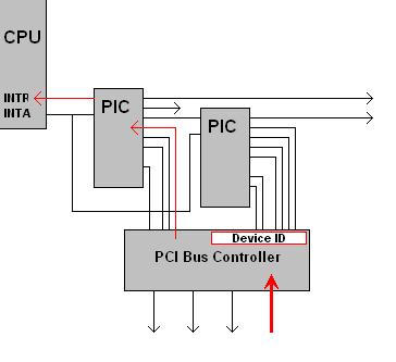
When a PCI device needs its driver code to run, it activates a PCI bus interrupt. The PCI bus controller determines which device has activated the PCI interrupt and stores this value in an onboard register (may be several values, it is the idea here that counts). Then the PCI bus controller activates any classic IRQ line not currently in use by another device:
-
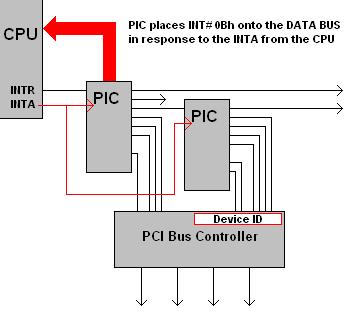
The CPU responds with an INTA and the PIC places the interrupt number onto the data bus as expected:
-
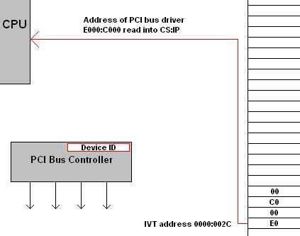
However, the Interrupt Vector Table holds the PCI bus controller's device driver address which the CPU fetches and begins to execute (not the device driver of the device that has requested service):
-
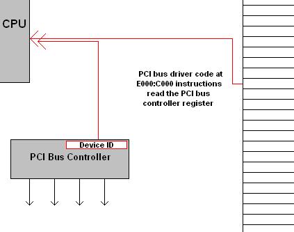
The PCI bus controller's device driver code reads the PCI bus controller's register and gets the identity of the device that actually requested service from there:
-
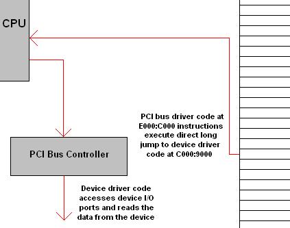
The PCI bus controller's device driver code executes a long RAM jump directly to the address of the driver code of the device that originally made the request. That code then proceeds to service the device:
-
When complete the device driver will execute a long jump return, which will land back at the PCI bus controller driver code. That code will execute the IRET which will clear the interrupt handling condition and place the CPU back at the program it was executing before it was interrupted. Note that because the PCI bus controller is the one that is attached directly to all of the classic IRQ's it can place its own driver code address throughout the IVT and use any IRQ to get to its own code which will in turn be able to launch any driver code based on the device ID it finds within its own registers. This is the process that Windows is referring to as "IRQ Steering" and the entries are called "IRQ holder for IRQ Steering" which means the IVT entry is present that will jump to the PCI bus controller's code which will then launch the device's driver itself.
-
Reboot and enter the BIOS. Change the setting of the LPT port to be LPT2 Save and Exit. Restart Windows in Normal mode.
-
Check the resources being used by the parallel port in Windows using MSINFO32. Record the resource and sharing changes that occurred. Shutdown properly.
-
Wiring Diagram of the PICs:
-
List the Industry Standard IRQ Assignments in order of priority:
IRQ# Device (optional/nonstandard devices in parentheses) -
List the IRQ Assignments reported by Device Manager:
IRQ# Device -
List the IRQ Assignments Displayed by Windows System Information (MSINFO32):
IRQ# Device -
List the IRQ conflicts and sharing as reported by MSINFO32 (with ACPI enabled):
IRQ# Device -
List the IRQ conflicts and sharing as reported by MSINFO32 (with ACPI disabled):
IRQ# Device -
List the IRQ conflicts and sharing as reported by MSINFO32 (after changing LPT1=>LPT2):
IRQ# Device -
List the BIOS settings (of the lab system) that can be used to control IRQ Assignments:
Setting Name Value -
List the ACPI IRQ assignment tables available to Windows in order of priority and place a check by those that Windows will attempt to use:
IRQ Table Name Check
Copyright©2000-2007 Brian Robinson ALL RIGHTS RESERVED