CET1172C Lecture #2 - External Ports and Modems
Materials: Working complete PC running Windows 98Modem and its drivers. Working complete PC running Windows 98Modem and its drivers.Objectives: The student will become familiar with: The various external port technologies and,Each technology’s functions and capabilities,The technical details of each technology,Know the optimal application, usage and implementation of each technology.Competency: The student will become familiar with the various external port technologies including their features, capabilities limitations and be able to choose the best one for a given expansion as well as be able to select the best solutions and upgrades and be able to troubleshoot these technologies. |
The original IBM PC featured two main types of "generic" external expansion/peripheral device ports: The serial port and the parallel port.
The serial port features the male DB9 and DB25 connectors on the back of the system. The OS refers to these ports as COM1, COM2, COM3, and COM4. Here are the system resources claimed by these ports:
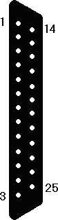
Serial Port I/O Base Address IRQ COM1 3F8h 4 COM2 2F8h 3 COM3 3E8h 4 COM4 2E8h 3 This is how the system interacts with a COM port, but what is a COM port? It is a UART (Universal Asynchronous Receiver/Transmitter) chip. This peripheral device is integrated into the modern motherboards through the ISA bus and it is also attached to the male DB9 or DB25 on the rear panel of the system. The device can accept a byte of data from the CPU through its I/O Addresses on the ISA bus and the CPU can also send it commands concerning how to transmit and receive data (also received through the I/O Addresses). The UART will establish communications with the other UART on the cable through a very simple exchange of signals on the lines. Then the UART will transmit the byte one bit at a time down the transmit line. Here is the DB9 pinout on the back of the PC:
The UART has lines for receiving data (Pin 2) and transmitting data (Pin 3). This indicates that depending on the UART, it can be a full duplex device meaning that it can transmit and receive simultaneously like a telephone. Half duplex (older UARTs) can only send or receive at a given time, like a radio. Simplex is one way communication like a coach yelling at the team through a bull horn. In that case communication can only go in one direction. The UART has always been a half duplex or full duplex device featuring two way communication.
When programmed through the I/O addresses the UART can be made to establish communications with another UART through the handshaking signals on lines 4, 6, 7, and 8. A UART that wishes to establish communications with another one will activate the Data Terminal Ready (Pin 4). The other device must respond with a Data Set Ready (Pin 6) signal. At this point, both UARTs know that they are "up and running." If the UART now wants to begin transmitting it will activate the RTS - Ready To Send (Pin 7). When the other UART is prepared to receive the information it will respond with a CTS - Clear To Send (Pin 8). At that point the UART will transmit one byte by sending it bit-by-bit over the Transmit Data line (Pin 3). The other UART is listening to the Receive Data line (Pin 2) for the data. As it arrives, that UART will catch it bit-by-bit and place it into a byte cell of RAM onboard the chip. When the byte has been filled and checked (if parity is being used) the UART will fire its IRQ line. The processor will pause what it is doing and execute the interrupt request. In the case of COM1 using IRQ4 this would be 8 + 4 = 12 or INT 0Ch. The instructions there will have the CPU read the appropriate I/O address in the 3F8h to 3FFh range where the UART has placed the byte so it can be read by the CPU. Now the CPU can save it anywhere in RAM that it needs it, effectively handing it up to the OS. The OS will resume after the interrupt and hand the byte up to the application which will then display it on screen (in the case of Internet Explorer retrieving a webpage, for example).
The DB25 is based on the old RS-232 serial communications technology which is no longer used, but an RS-232 device can establish communications with a UART which is why its connector is accommodated. The above signals are part of the RS-232 specification but run to different pins of the DB25 connector. As such an adaptor from DB9 to DB25 will work.
The original UART was an 8-bit Intel 8250. The IBM AT featured a 16-bit bus capable 16450. Note that the chip still sends and receives 8-bit bytes and its command set is still the same, but it can work on the 16-bit ISA bus of the AT. The 16550 introduced a 16 byte (character) FIFO - First In First Out, buffer. This allows the UART to store bytes as they arrive so that if the Interrupt request is not fulfilled fast enough, then the arriving bytes will not erase the preceding ones. As the interrupt request executes it will read from the top of the buffer, rather than from the arrival byte buffer hence it will retrieve the first byte that arrived (First in First out). The FIFO unfortunately did not function properly and had to be disabled. The 16550A fixed this, but the software had already been written to avoid using the faulty FIFO. The OS could not query the device to see if it was a nonfunctional 16550 or a functional 16550A. Therefore the 16550AN was made which can tell the OS (during POST and driver installation and OS setup) which chip it is. National Semiconductor bought the UART from Intel back in the 8-bit days and currently makes the 16550D. With a functioning FIFO the UART can establish a maximum communication speed of about 115,200 bits/second.
National Semiconductor licenses the UART to motherboard manufacturers so that they can embed it in the motherboard south bridge chipset. These manufacturers have moved on to the 16650 w/32-byte FIFO (230Kbps), 16750 w/64-byte FIFO (460Kbps), 16850 w/128-byte FIFO (920Kbps). External devices with better than modem speeds, such as ISDN or fractional T-1, would have to use one of these better FIFOs in order to keep up with the data transmission rates of these technologies.
Modem communication standards. The main device attached to the UART is a modem (MOdulator/DEModulator) which converts raw digital data bits on the serial line into sound waves to travel out the phone line. This process of converting the UART's pure digital serial data into sound is called modulation. When sounds are received and converted back into raw digital data bits for transmission back to the UART, this is called demodulation. There exist modulation standards which describe how a modem will convert digital data into sound waves suitable for transmission over the telephone lines. There also exist Error Detection protocols and Data compression protocols. Here are the "V dot" standards as they evolved:
Standard Technology Introduced V.21 300 baud/300bps using FSK V.22 600 baud/1200bps = > to 600bps using DPSK V.22bis 600 baud/2400bps = > 1200bps using QAM V.32 2400 baud/9600bps < = > 4800bps using QAM/TCM V.32bis 14,400 bps < = > 12,000, 9600, 7200, and 4800bps, 6bit QAM/TCM V.34 28.8Kbps < = > 24Kbps, 19.2Kbps and backwards compatible with V.32/V.32bis V.34+ Adds 33.6Kbps < = > 31.2Kbps or V.34/V.32bis/V.32 V.42 Adds LAPM/MNP1-4 "Error Correction" protocols V.42bis Adds another data compression scheme for use w/V.42 using MNP V.44 Adds Lempel-Ziv-Welch (LZW) compression algorithm V.90 Same speed (56Kbps) as Rockwell K56flex, and 3COM/USR x2 V.92 New Quickconnect protocol, Modem-on-Hold support (call waiting), PCM Upstream for 48Kbps uploads Where = > means "with fallback to" and < = > means "fallback and fall forward between"
Note that when you read the table above then V.21 has a fixed baud of 300 and a fixed data rate of 300 bps. V.22 has a fixed baud of 600 and can use DPSK to achieve data rates of 1200bps or 600bps depending on conditions. These modems are not necessarily compatible with V.21 modems. V.22bis modems still use 600 baud but use QAM to achieve data rates of up to 2400 bps and can fall back to 1200 bps. These are not necessarily backwards compatible with V.22 modems. V.32 supports a maximum data rate of 9600 bits/second at 2400 baud and can fall back and forward with a data rate of 4800 bps and it uses QAM and/or TCM to accomplish this data rate. V.32 modems are not necessarily backwards compatible with the V.22bis or older modems. V.32bis adds the 14,400 bps (14.4Kbps), 12,000 bps (12Kbps), and the 7200 bps data rates to the existing V.32 standard and can fall back and forward between these speeds and these modems are compatible with plain old V.32 modems. This is where the backwards compatibilities begin as part of the specifications. V.34 adds the 28.8Kbps, 24Kbps, and 19.2Kbps data rates and is backwards compatible with the V.32/V.32bis modems and so on.
A word on "baud" and "bits per second". J.M.E. Baudot was a French pioneer in telegraphy in the 1800’s who solved a critical problem concerning how to encode information in the telegraph. Because of his work the telegraph became a viable working technology for information exchange. The unit baud named after him refers the changes in the carrier wave of a communication wire and is therefore synonymous with the term frequency in this discussion. baud is usually used when the medium is a wire and the carrier wave is sound. Bits per second means the data transfer rate which is not necessarily equal to baud because the engineers found ways to sneak more bits into a wave than just one. FSK means Frequency Shift Keying, the standard of the telephone company itself for many years. Each data bit is associated with a particular frequency so a bit requires one entire sound wave to be received. In FSK 1 baud = 1 bit. DPSK means Differential Phase Shift Keying. In this method changes in the middle of the wave can be interpreted as a 0 or a 1 depending on the wave transition state. 1 baud = 2 bits. QAM is Quadrature Amplitude Modulation in which 1 baud = 4 bits. Trellis Code Modulation is another method of encoding larger numbers of bits into the waves. Later versions are fundamentally different but can squeeze 6 even 9 bits/baud.
- From V.22 on all of these technologies feature fallback. If line integrity is compromised during transmission, the modems will retry at slower rates until the transmission is error free. From V.32 on, all of the successive technologies feature backwards compatibility. So V.92 modems can establish a connection with V.32 modems. From V.32 on, modems can not only fallback but also fall forward. As line integrity improves, the modems can increase the transmission speed.
LAPM means Link Access Protocol for Modems and defines and logical handshaking language within the data being transmitted. It helps the modems tune each other to the same baud rates (the solid tones when your modem connects), and then ask each other "Can you speak at 2400bps?" the other answers in V.32 "Yes I can", the originator then asks "Can you speak at 4800bps?", the other answers in V.32bis, "Yes I can", this proceeds until the target does not answer. The originator then falls back to the last to the last "Yes I can" and the two proceed. LAPM incorporates this and the concept of transmitting discrete packets of data between the modems. Each packet would have a header describing its length and a CRC byte for checking that the data was not corrupted in transit. If it was, the receiver can request that packet again. This is the "Error Correction" being used. MNP means Microcom Network Protocol a proprietary technology developed by Microcom. It is a protocol using packets like LAPM but is different. It was introduced with Levels 1 through 4. MNP 5 greatly improves the data compression and level 10 supports damaged transmission lines while level 10EC is used by cellular telephone network modems.
V.90 was introduced specifically to avoid a problem that was emerging at the time. Rockwell, a modem chipset manufacturer, and US Robotics another industry leader in modem manufacture independently developed modem data compression techniques that could achieve data transmission rates of 56,000 bps over normal telephone lines. Rockwell called their technology "K56flex" and US Robotics called theirs the "x2" technology. Both are capable of 56Kbps but they are not compatible with each other and the ITU (International Telecommunication Union - formerly called the CCITT - Comité Consultatif International Téléphonique et Télégraphique) could see trouble brewing as each company sought to protect their technologies with patents. The ITU released the V.90 international standard that incorporated and superceded both the K56flex and the x2 technologies thereby forcing the two companies to stop fighting to try to "own" the modem market which was the main method of accessing the Internet at the time. V.92 improves on the connection delay time and provides native modem support for the telephone company's advanced features like call waiting.
Most modems use the Hayes AT command set. These are commands that are sent to the modem itself as a peripheral device as opposed to data that it will transmit. Hayes was an early producer of very high quality modems and realized that with the increasing complexity of the "V dot" standards and the communication requirements of the PC across the remote link to another computer that the modem would at times need to be sent configuration information during a communication session. Because of this, they developed a language with which to send commands to the modem while it is operating. Other companies adopted the Hayes command set for their modems for universal compatibility reasons and because the command set was sufficient to solve any modem's needs, so why reinvent the wheel? Here are some basic Hayes commands:
Command Meaning ATA or ATA0 Answer Call A/ Repeat preceding command ATB0, -B1,-B2 Support for entering older V.32 protocols ATDx Dial, for x modifiers see below ATH, -H0 On hook, Hang up ATH1 Off hook, Pick up ATI, -I0, -Iy Information, returns info about the modem, y proprietary values ATL, -L0 Off speaker volume ATL1 Low volume ATL2 Medium volume ATL3 High volume ATM, -M0 Speaker off, -M3 on some modems ATM1 Speaker on until connection established ATM2 Speaker always on ATV, -V0 Numeric result code ATV1 English result code (i.e. NO CARRIER) ATZz Reset modem, z is a digit for each configuration Be sure to complete the preparations section above before proceeding. Open Start > Programs > Accessories > Communication > HyperTerminal. This opens a folder that contains the Hyperterminal program. Double click it to open it. This splash screen is displayed:
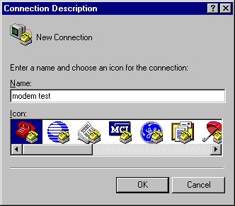
The following dialog box opens. Name the New Connection "modem test" (do not type the quotation marks) and leave the default icon selected and click the [OK] button:
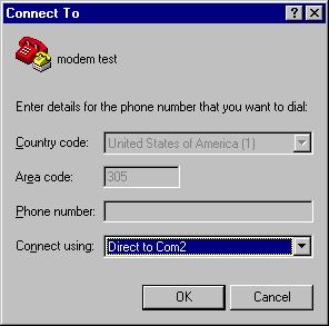
Now another dialog box opens asking for the telephone number to connect to. Hyperterminal is normally used to connect to remote machines using the modems. In this case, we want to communicate to the modem itself, not through the modem to another system. Pull down the "connect using" menu and select "Direct to COM2" as shown below and then click the [OK] button:
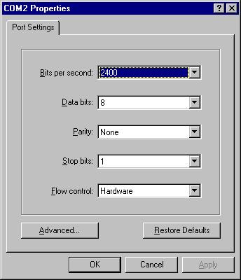
The system now asks for the comfiguration of the COM port (UART) itself. Leave all of these defaults and click the [OK] button:
At the Hyperterminal prompt type the [Enter] key a few times. Nothing will appear to happen, but this does warn the modem that commands are coming. Now type in "ATE1V1" (without the quotations!) and press [Enter]. This is the Hayes modem command to instruct the modem to enter into interactive mode. The modem will "echo" back the characters as you type them and also display its responses in plain text. Its response after you hit [Enter] should be "OK" on screen. Now type "ATI" then [Enter]. The modem will indicate the speed at which it is currently going to try to communicate in bps. Now enter the command to dial the telephone number (305)123-4567 and then hit [Enter]. In the open lab the modem should respond with "NO DIALTONE" since we have no active telephone lines in the room, but you should hear the modem attempt to connect and then see its response. Now enter the command to reset the modem and hit [Enter]. At this point your display should look similar to this:

Feel free to experiment from the Hayes command set above to see how the modem reacts. When you are done close Hyperterminal. The program will warn you that you are still connected and if you want to disconnect now. Click [Yes]. Then the program will ask if you want to save the session modem test? Click [Yes] and it will be saved by that name in the Hyperterminal folder so that you can use it again without having to reconfigure it.
Parallel ports. The female DB25 port on the back of the PC is the port for this peripheral device. Even though it is a clearly defined device it does not appear to have a generic Intel part number because it has appears to have always been constructed from generic third party basic components. The parallel port resources are:
Parallel Port I/O Addresses (1 or 2 ports) I.O Addresses (3 ports) IRQ LPT1 378h-37Ah 3BCh-3BFh 7 LPT2 278h-27Ah 378h-37Ah 5 LPT3 - 278h-27Ah 5 The device establishes communication with the remote device with similar techniques used by the UART. More code is required in addition to the hardware to recognize and deal with the signals on the lines. The parallel port has evolved from the original PCs 8-bit unidirectional port to the latest high speed parallel ports:
Port Input Output Resource/Notes SPP - Standard Parallel Port 50KB/s 150KB/s Input is 4 bit Bidirectional Port (SPP) 150KB/s 150KB/s Input modified to 8 bit EPP - Enhanced Parallel Port I/O=500KB/s - 2MB/s New controller ECP - Enhanced Capabilities Port I/O=500KB/s - 2MB/s Uses DMA 3 The Parallel Port is wired as follows:
1. Strobe, Output
2. - 9. Data bit 0 - 7, Output
10. Acknowledge, Input
11. Busy, Input
12. Paper end, Input
13. Select, Input
14. Auto Feed, Output
15. Error, Input
16. Initialize Printer, Output
17. Select Input, Output
18. - 25. Data bits 0 - 7, InputThe IEEE 1284 standard governs this port including the BIOS code support, through the pin outs through the operation of the EPP and ECP controllers and the cable quality.
USB means Universal Serial Bus. USB is a nonprofit entity funded by many companies in the PC industry. The technology has been developed to incorporate external devices at far greater speeds than the old UARTs support and to be able to autoconfigure and/or load drivers using the Plug-n-Play standards of the PCI bus. To this end it has been an end user success.

The original product box logo for USB devices
The USB symbol found on devices, cables, connectors, etc.
USB 1.1 was a slight modification of the original technology (a bug fix) and is considered the early standard. The main difference between USB 1.1 and 2.0 is the speed. USB 1.1 supports two different speeds or channels. "Low Speed channel" has a serial data transfer rate of 1.5Mbps. "Full Speed channel" has a data transfer rate of 12Mbps. Slower devices like keyboards and mice are built to use the Lo channel. USB 2.0 includes full backwards compatibility plus a new "Hi Speed channel" at 480Mbps channel.

The product box logo for USB 2.0 compliant devices.
The USB controller can identify up to 127 devices (meaning there are 128 device IDs and the controller claims one ID). These devices are connected in a star topology through dedicated USB hubs.
USB will only work in the presence of a functioning bus host controller which coordinates all devices and traffic on the bus. Devices function in a "speak-when-spoken-to" mode. They only transmit when a host controller requests it.
USB features an "A" connector and socket/receptacle. The PC's host controllers have the "A" receptacle that is flat and narrow. The external devices feature a "B" receptacle that is more square. A USB cable from host controller to external device then has an "A" connector on one end and a "B" connector on the other. This is done because the cable has four wires: 1. +5VDC power (red), 2. -Data (white), 3. +Data (green), and 4. Ground (black). A fifth wire is sometimes encountered and is attached to the shield surrounding the 4 inner wires. If you plugged a straight through cable from one PC to another you would be connecting +5VDC to Ground in both directions, short circuiting both PCs which would result in rising columns of smoke from both of them! This is why the ends of the cables have different connectors, making sure that you will not inadvertantly try such a thing.
USB devices may only pull 100mA of current through the USB cable from the controller source at start up. They may request increases in 100mA increments up to a maximum of 500mA. Devices attached to a USB hub may only request 400mA. This may cause some devices to malfunction when attached to hubs that work fine when plugged directly into the host controller's port.
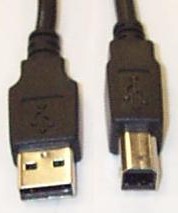
Standard USB Connector ends of an external USB cable:
"A" Male on the left and
"B" Male on the right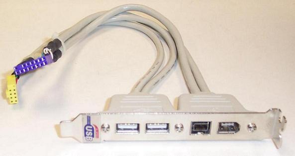
USB Connector ends of an internal USB Motherboard Expansion Slot Adapter:
Two 4-pin IDC with ninth key pin (yellow connector) on the left and "A" Female on the right
(the other connectors are 4-pin FireWire -small and black- and 6-pin FireWire)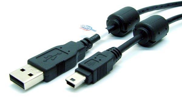
Standard USB Connector ends of an external USB cable:
"A" Male on the left and
5-pin "mini-B" Male on the right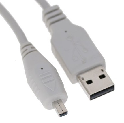
Standard USB Connector ends of an external USB cable:
"A" Male on the right and
4-pin "mini-B" Male on the left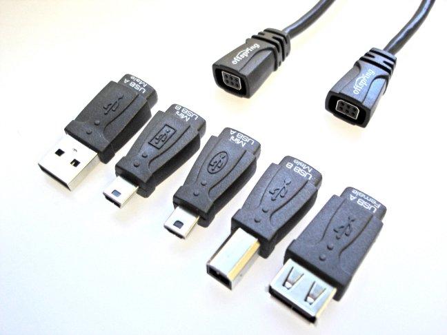
Standard USB Connector ends of a 5-in-1 cable adapter USB cable:
Of particular interest is the "mini-A" in the center and
the "A" Female on the rightPowered USB, based on the USB PlusPower speification addendum to the USB 2.0 Specification allows devices to use up to 6A at either 5VDC, 12VDC, or 24VDC. This is a lot of wattage. Most standard USB cables would not be recommended and the devices may not function due to a standard USB host controller's inability to recognize their high powered requests. This technology is seen most frequently in modern Point-Of-Sale hardware such as check out line laser bar code readers.
Host controller's themselves come in three forms: OHCI - Open Host Controller Interface developed jointly by Compaq, National Seminconductor and Microsoft. UHCI - Universal Host Controller Interface developed by Intel and EHCI - Enhanced Host Controller Interface which is the single backwards compatible USB 2.0 capable host controller. All USB devices are required to work with OHCI and UHCI devices. USB 2.0 capable devices are required to work with all three. All modern drivers can recognize and work with any of the three but older drivers may not work with certain host controllers.
The USB host controller usually claims IRQ 11 and very high I/O addresses above FF00h. But this is not etched in stone because it was invented after the release of PCI and is a true Plug-n-Play device made for the PCI bus. As such it can function using any resource and the drivers will support this behavior. USB support was added to Microsoft operating systems starting with Windows 95 OSR2, though Windows 98 has better USB support. But even Windows 98 has problems recognizing the subsequent attachment of some USB devices that have already been attached and had their device drivers loaded. Windows ME and Windows 2000 finally resolved these issues and work well with USB devices.
Signaling in USB uses a coding called NRZI - No Return to Zero Inverted. The physical signal integrity is maintained by sending the zeros and ones in opposite voltage polarity on two separate wires (-Data and +Data). The transceivers actually read the voltage differential between the two wires as signals. This allows for much lower voltages to be used and helps defeat signal attenuation over long distances. This method of signaling is refered to as balanced or voltage differential signaling, a technique that has been used by SCSI since its earliest architectures.
-
NRZI is a faster and more reliable method of transmitting serial data than most others and it allows the transmitting and receiving devices to synchronize their clock cycles as part of the transmission; a feature not shared by most other data transmission methods. In reality, the voltage changes in the transmitted data stream supply the clock cycle to the receiving device. For NRZI:
- A binary "0" will be represented by a voltage change during the clock cycle
- A binary "1" will not involve a voltage change during the clock cycle.
- If six binary 1's occur in succession, a voltage change bit will be "stuffed" into the transmission so that the receiving device can stay in synchronization with the transmitting device.
The byte, 01110001, will look like the following illustration assuming that the signal wire was at a high voltage state prior to the first "0":
The first "0" causes the voltage to fall (change), the next bit is a "1" which causes no change, the next bit is another "1" which causes no change, the fourth bit is another "1" - no change, the fifth bit is a "0" which causes a change (to high), the sixth bit is a "0" which causes a change (to low), the seventh bit is a "0" which causes a change (to high), and the eighth bit is a "1" which causes no change (stays high) as the transmission proceeds off the edge of the bits that we have monitored.
FireWire is a defined external serial interface technology based on the IEEE 1394 specification. This is a technology that has been borrowed from Apple Computers where it was first developed in an effort to make a fast, easily configured alternative to SCSI. Incidentally, FireWire has been redefined as a form of Serial SCSI and actually falls under the latest SCSI specifications. It might have been more welcome into the PC market if the PC market had not already spent so much money and effort on USB which incidentally was as much a reaction to FireWire as it was to the slow and unfriendly (read: non-Plug-n-Play) external peripheral ports that had been available.
FireWire is also a high speed serial technology, but that is where the similarity ends. FireWire supports up to 63 devices (uses 64 IDs, one is used to broadcast). The topology is a daisy chain indicating a bus in which the end devices autoterminate. There is no fixed host controller, so there can be none, one, or many. Individual devices may intiate communication at any time with any other device, unlike USB devices that must only communicate when told to so by the host controller of which one and only one must exist on each USB bus or nothing will work. FireWire currently supports speeds up to 200Mbps/400Mbps/800Mpbs with plans for up to 2Gbps and beyond.
FireWire recommends no more than 4.5Meters between devices. USB maximum cable lengths are 5M. Both technologies fully support Plug-n-Play and hot swapping of devices. USB appears to be the PC standard and is well supported logistically and monetarily by the PC's largest companies so PC users should stay with USB since it is well established and supported by the PC market and is built into and standard on most modern south bridges of the motherboard chipsets meaning that all USB devices will work on all modern PC's. This is not necessarily the case with FireWire.
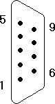 |
1. Carrier Detect, Input 2. Receive Data, Input 3. Transmit Data, Output 4. Data Terminal Ready, Output 5. Ground, Electrical (Neither) 6. Data Set Ready, Input 7. Request to Send, Output 8. Clear to Send, Input 9. Ring Indicator, Input |
Fill in the table:
Serial Port I/O Base Address IRQ Fill in the table:
Port I/O Address (1 or 2 ports) I/O Address (3 ports) IRQ What is the input transfer rate and data width of the unidirectional SPP?
What is the transfer rate and data width of the Bidirectional Parallel Port?
What is the range of transfer rates and the main difference between EPP and ECP?
What modem standard uses FSK, what is its baud and transfer rate in bits/sec?
What modem standard uses DPSK, what is its baud and max transfer rate?
What was the first standard to use QAM, what was the baud and transfer rate?
What was the first standard to be fully supported by subsequent standards (they will fallback to it), what was its baud and transfer rate(s)?
What standard introduced 33.6Kbps modems?
What standard introduced "error correction", and how does it really work?
What modulation standard is associated with the above error correction standard, what is its max speed, what proprietary standards did it supercede (obsolete)?
Name the two handshakes that the UART can perform with an external device and the pairs of wires used (not the pin numbers, the names)?
Name the data line(s) of the DB9 (the pin numbers and the names) and which is input and output and what form of communication is possible.
A null modem cable is used to attach two PC serial ports directly to each other, by crossing over the input lines of one to the output lines of the other. Based on the information provided in this module, sketch the pinouts of a null modem cable:
Give the Hayes modem commands to do the following:
Reset the Modem:
Hang up:
Set the speaker to always on:
Get Information from modem:
Set the volume to low:
Answer an incoming call:
Repeat previous command:
Use Pulse Dialing:
Dial last number:
Turn off the speaker (not volume):
Pause during dialing:
Fill in the table:
Parallel Port Input Output Notes Name the input data pins on the female DB25 connector. Name the output data pins.
Prior to the Bidirectional parallel port in which the input data bit pins were defined programmers designed special drivers that could pick up information from external devices but only 4 bits at a time could be used. Check the pin out and figure out which lines they used to transfer the data to the PC that were never intended to be used this way.
List the features of USB:
Max # of Devices/IDs:
Maximum single cable length:
Host controller required (Yes/No):
Type of physical topology:
USB 1.1 speeds (Hi/Lo channels):
USB 2.0 speeds:
Encoding method:
Physical transmission method:
Initial amperage of a device:
Max. amps of a device on a hub:
Max. amps of a device on the host:
List the features of FireWire:
Max # of Devices/IDs:
Maximum single cable length:
Host controller required (Yes/No):
Type of physical topology:
Maximum speed(s):
Proposed maximum speed:
List features common to the two technologies (USB/FireWire):
What was the first Microsoft OS to feature USB support?
What OS features better support for USB and which one's feature full and reliable implementation of USB support?
Where do you find the USB connector:
Male "A":
Female "B":
Female "A":
Male "B":
Copyright©2000-2004 Brian Robinson ALL RIGHTS RESERVED