MSM2 Lecture #6 - Video Controllers
Materials: Working complete PCStudent bootable floppy diskette - "New Boot A Version 2" Working complete PCStudent bootable floppy diskette - "New Boot A Version 2"Objectives: Understanding of how video controllers work,Discuss the generations of video controller,Discuss PC video graphics standards,Discuss PC video graphics technologies,Discuss PC video graphics chipsets,Be able to identify the video controller,Understand the video controller expansion interfaces.Competency: The student will become familiar with the evolution of the video controllers from early implementation to the present. The student will understand how the video controller works in both standard VGA text modes and graphics modes. The student will learn about the various industry standards for video controllers. The student will understand the fundamental functionality of this resource and be able to list all related technologies. The student will be able to determine the video controller attached to the system and be able to change settings when possible in BIOS and Windows. |
-
The instructor will issue each student a complete system unit, monitor, keyboard, and mouse.
-
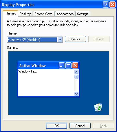
Boot the PC into Windows 98 Normally. Right click on the desktop and select properties. The Display Control Panel applet is the standard location where the basic settings of the video controller can be changed, but it is important to note that almost all modern controllers are SVGA - Super Video Graphics Array controllers. SVGA controllers by definition: conform to the industry standard VGA specifications and may then implement any proprietary technology that the manufacture chooses. Because of this, the standard Windows Display control panel applet may not have the ability to take full advantage of the video cards various capabilities.
-
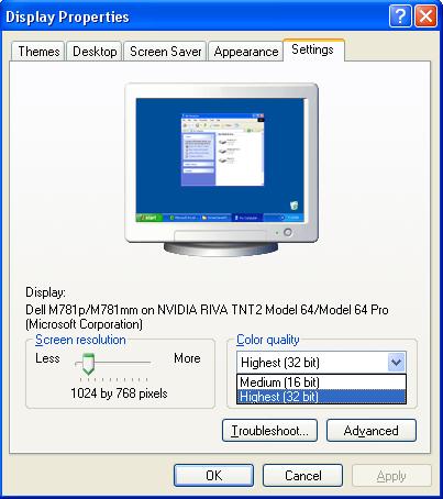
Click on the Settings tab. This diaplsys the current resolution settings of the video card in graphics mode (Windows uses only graphics modes, never text modes). Note the current pixel resolution (in the example below it is set to 1024 x 768) and the current color depth (in the example below it is set to 32-bit Color). Now change the pixel resolution slider from minimum to maximum. What are the minimum and maximum ranges of the card? Pull down the color depth choices. What choices are available?
-
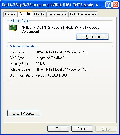
Be sure the pixel resolution is unchanged as well as the color depth and click on the Advanced button. This opens another applet window. Click the Adapter tab. This displays the adapter type including the identified chipset on the adapter at the top. In this case it is an Nvidia RIVA TNT2 Model 64/Model 64 Pro chipset based video card. Note that the statement "(Microsoft Corporation)" indicates that the operating system is using its own driver for the card. This may work, but it is highly recommended that the OEM drivers for the video card be installed anyway. These will almost always allow the system to be able to set more possible resolutions, color depths, and refresh rates. Other advanced settings may also not be accessible at all until the OEM drivers are installed.
-
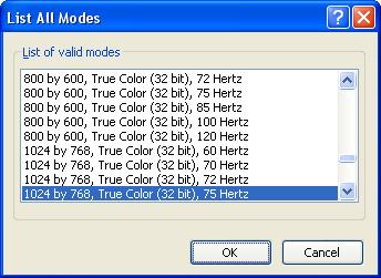
Click on the "List all Modes..." button. This shows every possible combination of pixel resolutions, color depths and refresh rates that the driver can set the video card to. Again this may not be complete without the OEM drivers installed.
-
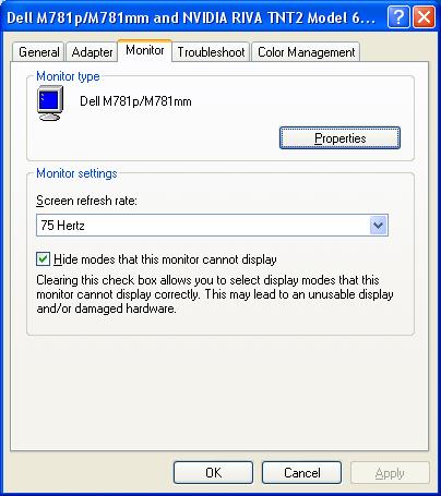
Do NOT change the mode from this window. Close it and click the Monitor tab of the Advanced settings window. The monitor is a Plug-n-Play device which the operating system has identified. This tab sheet reports it as a Dell M781p/M781mm. Incidentally it is running off of the generic display drivers of the operating system as well. Again, the OEM drivers may be able to achieve superior performance. Note that the checkbox labeled "Hide modes that this monitor cannot display" is checked. This is crucial. Most modern video cards can send output to a CRT - Cathode Ray Tube (picture tube) type display that the tube physically cannot handle. Most monitors will attempt to display the image anyway. This can quickly destroy the monitor. By hiding modes that the monitor cannot handle ensures that the user will not select a setting that could potentially destroy it. Again, this would be a much safer situation if the OEM drivers that came with the monitor were installed. Manufacturers often make changes to the design of their devices that could render the Microsoft drivers obsolete and potentially dangerous, in this case they might allow a setting in this box that the monitor actually cannot handle.
-
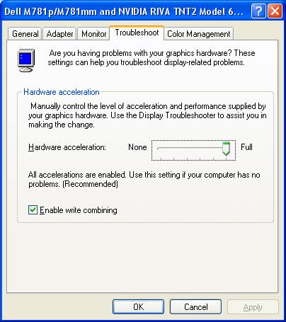
Be sure not to make any changes in this tab sheet and click on the Troubleshoot tab. Microsoft's generic Advanced settings applet does not offer much in the way of true troublshooting the device. Suffice it to say, that if it is really acting up, then we would not be able to see anything to be doing anything anyway! The one setting that can be adjusted here is the "Hardware Acceleration" slider. Virtually all modern video cards feature some form of onboard processor called the GPU - Graphics Processing Unit. These are in many cases very powerful microprocessors themselves rivaling the CPU of the PC itself in raw speed and throughput. However, they have been designed specifically to receive special graphics language instructions like "DrawCircle(Center at X, Y, Diameter = Z, Color = W) This instruction may be encoded in as little as 64 bits, but the bitmap of the entire circle on screen may consists of thousands of pixels, each 32 bits in memory size. The GPU receives the instruction and proceeds to make the calculations itself and creates the circle in a video page of RAM built into the video controller. This slider then attempts to reduce reliance on the GPU, but this forces the operating system to hand all of the graphics calculation work back to the CPU. This would dramatically bog down the performance of the system and should only be done if the video controller's GPU is suspect.
-
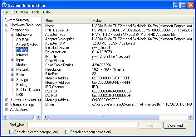
Cancel all open applets and then click Start > Run and type "MSINFO32" in the text box (no quotes!) and press [Enter] This opens the System Information Diagnstic Utility. As demonstrated in other exercises, this tool can be much more powerful and reliable than the Device Manager. Click the [+] in front of Components in the left side window pane then click directly on "Display" The right hand window pane describes the adapter and the drivers in detail including the system resources that the adapter is using. Note that the video controller is the one standard device that uses normal RAM as its most significant system resource. Most other modern high speed devices now do this, but it was the video controller that did this first.
-
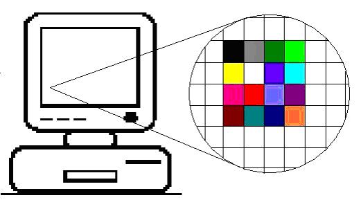
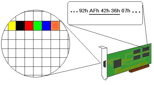
Video controllers are equipped with at least: RAM scanning controller chip, graphics processor, onboard video page RAM, the RAMDAC - Random Access Memory Digital to Analog Converter. The RAM scanner automatically and continuously reads a segment (or more) of regular RAM. Whatever it finds in this region is then interpreted by the graphics processor, the results of which are held in the video page RAM onboard the video controller, the video RAMDAC then scans the video page RAM and adjusts its output voltages for the Red/Green/Blue intensities being sent by the video cable to the monitor which then displays colored squares on screen. These colored squares are called pixels which is a contraction for the term "Picture Element." Pixel resolution is then the measurement of how many pixels wide the screen has been divided into by how many high.
-
VGA - Video Graphics Array, became the industry standard when the GUI - Graphical User Interface, began to emerge in the PC industry as a future standard in coming operating systems (Windows 9x). Before this, there existed many different video standards that were essentially proprietary. By setting up an open architecture video standard the industry assured the end user that graphics-based OS's would be able to load up and boot and be viewable on any PC regardless of the video card installed on it.
-
VGA is formally defined by its resolution and color depth. VGA is "640 x 480 in 16 of 256." The first two numbers are the screen graphics resolution in pixels across by pixels high. So the VGA screen is a maximum of 640 pixels across by 480 pixels high. The third number means the maximum number of colors that the video controller can represent on screen at one time. For VGA this is 16 colors. VGA supports a color palette of 256 possible colors.
-
The video controller can be instantly changed from using 16 particular colors assigned to the 16 different numbers representing each bit, into any other arrangement of 16 colors for the 16 numbers. So VGA can display 16 colors at a time and switch between any combinations of 256 possible colors in a color palette.
-
At any time one, some or all of the 16 colors could be redefined with a new color from the palette. Even the palette can be reloaded, but this would probably not be efficient during the course of a program's execution. The full definition of VGA is then: 640 columns by 480 rows of pixels, each pixel can be one of 16 preset colors taken from a palette of 256 possible colors. Or in shorthand try to remember:640 by 480 in 16 of 256. The industry has added 800x600 in 16 of 256 as part of VGA.
-
If each pixel can be one of 16 possible colors how many bits are required to store each pixel? 24=16. So each pixel is held in memory as a 4-bit value. The video RAMDAC chip on the video controller is responsible for constantly scanning the video RAM buffer. As it does so, it translates the values by their position in the RAM array into which pixel, and the value stored there will determine which color it should be.
-
In this example, the RAMDAC is displaying the underlined bytes as the colors shown in which the first four bits of the first byte which are the hexadecimal digit "A" are defined as the color yellow, the next four binary digits represented by the hexadecimal "F" are black, the next hex digit 4 = red, the next pixel in the row is represented by hex digit 2 = green, the next pixel is hex digit 3 = blue, 6 = orange.
-
So now how large is the VGA memory space? 640 x 480 = 307,200 pixels. Each pixel occupies 4 bits so: 307,200 pixels x 4 bits/pixel = 1,228,800 bits. There are 8 bits in a byte so 1,228,800 bits ÷ 8 bits/byte = 153,600 bytes ÷ 1024 = 150KB. So even 1/4MB (256KB) is large enough to support the highest resolution graphics mode of VGA.
-
So how does the VGA controller work in text mode? The RAM addresses starting at B8000h hold an ASCII code followed by a video attribute, these are not bit mapped images like the graphics modes in which each bit or group of bits represents the color of each pixel. In graphics mode the video chipset simply scans the area of memory that represents the screen and reads each group of bits and then sets the proper voltages on the Red, Green, and Blue control lines in the cable to the monitor during the correct moment of time during the raster scan of the monitor and the pixel will be created in the correct color in the correct position on the monitor screen.
-
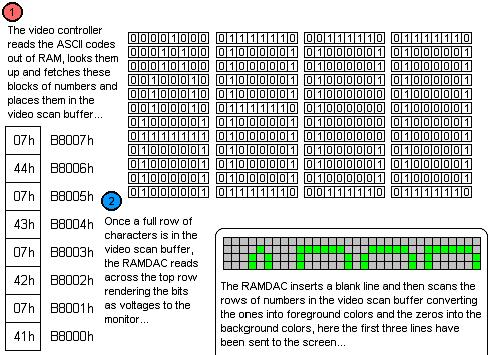
But in text mode, the video chipset scan the area of RAM and finds an ASCII code. To simplify the illustration of what the video controller does, assume that the screen is four characters wide and four lines high. The video chipset scans the area of RAM that represents the screen and finds the value 41h. This is then used in a look up table to find a block of numbers being held in another memory location. That block of numbers is loaded into another set of RAM locations built into the video controller chipset. The video attribute byte is read next and this controls the fore ground and background colors of the bits in the numbers held in the RAM built into the video controller. This RAM is the video scan buffer.
-
The next byte is read from the RAM location that represents the screen at address B8002h. It is 42h which is ASCII for "B" This is used to look up another block of numbers which are loaded into the video scan buffer. The next byte will control the colors of the ones and zeros of this block of the video scan buffer. The next byte at B8004h is 43h which is ASCII code for "C" This is again looked up against a memory lookup table and a corresponding block of numbers is read into the next block of locations in the video scan buffer. Next the video attribute byte for the "C" is read in, now the last character of the first line is read from B8006h and it is the number 44h which is ASCII for "D". This number is used to lookup a block of numbers that are copied into the video scan buffer. The next byte is read in which is the video attribute for the "D".
-
At this point one whole row of characters to be displayed on screen has been read from RAM, looked up and the blocks of numbers representing them have been read into the video scan buffer. Now the video scan buffer is read by the actual RAMDAC which sends the properly timed Red, Green, Blue voltage combinations through the cable to the monitor. The look up blocks are the little bit map images of each ASCII character code and that’s how they get converted into the images on screen. The look up table is held in the motherboard BIOS and there are several standard "ROM fonts" that are used depending on the VGA mode. Custom fonts can also be loaded into RAM and the video controller can use them to look up the ASCII codes instead of looking them up in the BIOS ROM. Aside from running faster, the user can define any character block bitmap for each ASCII code effectively designing custom fonts for use in console applications.
-
Note that VGA is fully backwards compatible with the older video standards. These are retained in VGA as the different modes that the VGA controller can be set to at any time. Note that when the VGA controller changes mode it resets and everything on screen is lost.
-
XGA was introduced by IBM to support their top of the line PCs and PS/2’s of the time. The controller supports a resolution of 1024 x 768 in 256 colors. The 256 colors requires one byte per pixel. So 1024 x 768 = 786,432 pixels x 1 byte/pixel = 786,432 bytes. So the video RAM required for XGA is significantly larger than VGA and these controllers needed at least 768KB of RAM which is exactly what they had installed on them. XGA also supports a resolution of 640 x 480 in high color. High color is the term that means 2 bytes are used to represent each pixel which can therefore be one of 216 = 65,536 colors. High color is very close to photographic quality.
-
XGA was quickly surpassed by the third party video controller manufacturers. But every video controller manufacturer was developing a different controller with different resolutions and modes. Pandemonium was about to ensue, what video cards would a particular piece of software support? Which ones would not be included in the Windows 95 installation CD-ROM? The software industry told the video card people to develop a standard or else. No one cared until Microsoft insisted.
-
Super VGA is defined as any resolution that is greater than VGA. However, the major part of the SVGA standard is that it includes pure VGA compliance. In order to manufacture a video card and acall it SVGA, it MUST adhere to the strict low level specifications of VGA first. Then it can switch from VGA into whatever mode and resolution that the manufacturer can possibly invent. This allows all modern SVGA video cards to startup and reset into a standard VGA text mode so that the BIOS screens will be visible and the system can proceed to boot into DOS with no problems. After that an operating system can function enough to allow the user to load the video card’s drivers and reboot. Again, the card will reset to standard VGA text mode and the BIOS and boot strap process will all be perfectly visible. Once the operating system begins loading drivers, then the card can switch into its native mode and its full graphics capabilities.
-
So 640 x 480 x 256 which is the same pixel resolution as VGA but with greater color depth per pixel (256 possible colors = 8 bits per pixel). Therefore this is an SVGA resolution. Despite this, SVGA has been formally defined as: 800x600 in high color or 1024x768 in 256 colors (8-bits/pixel). Calculate the memory requirements for 1024 x 768 in true color. True color is another graphics industry term and means that each pixel is represented by three bytes in video RAM or 24 bits per pixel: 224=16,777,216 colors. True color is a very high quality color depth that approximates photographic quality very well. There is also a "32-bit true color" which means what it says: 32-bits or 4 bytes are used to store the color information about each pixel. How much RAM does 1024 x 768 in true color need? 1024 x 768 = 786,432 pixels x 3 bytes = 2,359,296 bytes. So the minimum array would need to be at least 2½MB.
-
Incidentally, what is the aspect ratio of the standard CRT? Aspect Ratio means the ratio of its width versus its height. For television and therefore all of the CRT's that would be used in making PC monitors this ratio is 4-to-3 usually expressed as "4:3" And this is the ratio of all of the pixel resolutions that are being discussed in this lecture. It should be noted that flat panel technologies like LCD displays and plasma televisions no longer have to conform to this aspect ratio and many of these technologies are appearing as wide screen displays. Most video controllers however cannot render wide screen or unusual aspect ratios which therefore leaves the output looking "letterbox" style with unused black regions across the top and borrom of the display. Verify that 1024 x 768 is a standard aspect ratio. Divide 1024 by 4 = 256. Now multiply 256 by 3 = 768. The aspect ratio is therefore 4:3.
-
When the PC starts up the motherboard BIOS scans for external BIOS modules in RAM. If it identifies one (or more) it will pass control to the external BIOS and let it execute. The video card has one of these external BIOS modules and the motherboard will recognize it and pass control to it. This actually takes place prior to the POST itself. This ensures that the video card’s BIOS will get a chance to execute its own onboard BIOS POST code which can test and reset the card to the standard VGA text mode. Then it will return control to the motherboard BIOS to proceed with the POST. If this did not happen then the card might not be set to a standard VGA text mode and then the motherboard POST would not be visible on the screen, nor would anything from DOS including the prompt or output of any of the commands. This BIOS architecture is the reason why you will sometimes see a splash screen from the video card prior to the splash screen of the motherboard BIOS itself. The motherboard BIOS POST code passes control to the video controller BIOS immediately before the motherboard POST is executed.
-
Most systems motherboard BIOS expect the video controller to reset to VGA mode 3. Also the BIOS Setup Utility and DOS expect the card to be set to VGA mode 3 under normal circumstances. The base RAM address for the VGA controller’s RAMDAC chipset while in VGA mode 3 is B800:0000h. This is actually the graphical mode segment of RAM, but most modern systems use this segment for the text mode segment as well. Compaqs BIOS use the old standard VGA text mode base address of B000:0000h and are technically correct, but they appear to be one of the few systems that do this. Since their BIOS knows the correct address and DOS displays everything on screen through function calls to the BIOS, the system works in this VGA text mode with no problems. It should also be noted that VGAs resolution (640x480 in 16 of 256) is in actuality the highest possible resolution amid these defined modes; specifically it is mode 12h or VGA mode 18 in decimal.
-
Boot up a system running DOS 6.22 or a Windows 9x version. At the C: prompt clear the screen and then run DEBUG:
C:\>debug -_ -
DEBUG can be used to display the contents of any addressable RAM location on screen. Type the command "d b800:0 ff" and press [Enter]:
C:\>debug -d b800:0 ff B800:0000 20 07 20 07 20 07 20 07 - 20 07 20 07 20 07 20 07 . . . . . . . . B800:0010 20 07 20 07 20 07 20 07 - 20 07 20 07 20 07 20 07 . . . . . . . . B800:0020 20 07 20 07 20 07 20 07 - 20 07 20 07 20 07 20 07 . . . . . . . . B800:0030 20 07 20 07 20 07 20 07 - 20 07 20 07 20 07 20 07 . . . . . . . . B800:0040 20 07 20 07 20 07 20 07 - 20 07 20 07 20 07 20 07 . . . . . . . . B800:0050 20 07 20 07 20 07 20 07 - 20 07 20 07 20 07 20 07 . . . . . . . . B800:0060 20 07 20 07 20 07 20 07 - 20 07 20 07 20 07 20 07 . . . . . . . . B800:0070 20 07 20 07 20 07 20 07 - 20 07 20 07 20 07 20 07 . . . . . . . . B800:0080 20 07 20 07 20 07 20 07 - 20 07 20 07 20 07 20 07 . . . . . . . . B800:0090 20 07 20 07 20 07 20 07 - 20 07 20 07 20 07 20 07 . . . . . . . . B800:00A0 43 07 3A 07 5C 07 3E 07 - 64 07 65 07 62 07 75 07 C.:.\.>.d.e.b.u. B800:00B0 67 07 20 07 20 07 20 07 - 20 07 20 07 20 07 20 07 g. . . . . . . . B800:00C0 20 07 20 07 20 07 20 07 - 20 07 20 07 20 07 20 07 . . . . . . . . B800:00D0 20 07 20 07 20 07 20 07 - 20 07 20 07 20 07 20 07 . . . . . . . . B800:00E0 20 07 20 07 20 07 20 07 - 20 07 20 07 20 07 20 07 . . . . . . . . B800:00F0 20 07 20 07 20 07 20 07 - 20 07 20 07 20 07 20 07 . . . . . . . . -_ -
The output on the students computer may be different or may contain nothing. In that case try "d b000:0000 00ff" which is the alternate base address from which most (S)VGA controllers operate in standard text modes for BIOS and DOS 16-bit operation. Notice that DEBUG was asked to display the binary contents of RAM starting at segment B800h offset 0000 up to offset 00FF. This is the base address of the video controller RAM and indeed on RAM offset 00A0h something other than "20 07" appears and in the ASCII translation of these different numbers on the far right side of the row, it reads "C.:.\.>.d.e.b.u" and the "g" appears on the next line within DEBUG. That is what was on the screen at the top left corner when DEBUG started the D (Dump or Display on screen) command. The output of the D command appeared on screen after DEBUG read the area so the output does not appear in the output. (I think I know what I think I mean.)
-
DEBUG also allows the user to write new values into any RAM location. By the way everything is hexadecimal in debug and the 20’s are ASCII for spaces and the 07’s are the video attribute for black background and white foreground to be applied to the preceding character. A space is all background and no character, hence the deep horrifying black abyss of the DOS screen. Perhaps a lovely turquoise would have made DOS less intimidating? Type in "f b800:0000 0FFF 30" and press [Enter]:
00000000000000000000000000000000000000000000000000000000000000000000000000000000
00000000000000000000000000000000000000000000000000000000000000000000000000000000
00000000000000000000000000000000000000000000000000000000000000000000000000000000
00000000000000000000000000000000000000000000000000000000000000000000000000000000
00000000000000000000000000000000000000000000000000000000000000000000000000000000
00000000000000000000000000000000000000000000000000000000000000000000000000000000
00000000000000000000000000000000000000000000000000000000000000000000000000000000
00000000000000000000000000000000000000000000000000000000000000000000000000000000
00000000000000000000000000000000000000000000000000000000000000000000000000000000
00000000000000000000000000000000000000000000000000000000000000000000000000000000
00000000000000000000000000000000000000000000000000000000000000000000000000000000
00000000000000000000000000000000000000000000000000000000000000000000000000000000
00000000000000000000000000000000000000000000000000000000000000000000000000000000
00000000000000000000000000000000000000000000000000000000000000000000000000000000
00000000000000000000000000000000000000000000000000000000000000000000000000000000
00000000000000000000000000000000000000000000000000000000000000000000000000000000
00000000000000000000000000000000000000000000000000000000000000000000000000000000
00000000000000000000000000000000000000000000000000000000000000000000000000000000
00000000000000000000000000000000000000000000000000000000000000000000000000000000
00000000000000000000000000000000000000000000000000000000000000000000000000000000
00000000000000000000000000000000000000000000000000000000000000000000000000000000
00000000000000000000000000000000000000000000000000000000000000000000000000000000
00000000000000000000000000000000000000000000000000000000000000000000000000000000
00000000000000000000000000000000000000000000000000000000000000000000000000000000
-_
-
30h then is the ASCII code for zero, and 30 is the video attribute for the turquoise green background and the black foreground colors. Feel free to experiment with the F command filling the video RAM with values. The fill command can take two separate bytes like "f b800:0000 0FFF 30 07" which will fill the screen with white zeros on a black background and return the screen to the normal DOS video attributes. ASCII starts at 20h (the empty space) and goes to FFh with printable characters. However, video attributes should not have the same number in the first hex digit and the second like: 22 or 33, because it can set the foreground and background numbers the same. Then the screen will be solid and the user cannot see the command being typed either. Also any video attribute 80h or higher sets the highest bit to 1, which is the blink bit. It can be highly nerve racking!
-
The graphics card manufacturers had for several years during the reign of the 486 enjoyed the success of the VESA local bus as an expansion bus for their throughput hungry video cards. Intel introduced the new and much more powerful PCI expansion bus which had as much throughput as the VESA local bus without any of the shortcomings of it (attaching directly to the CPU with no chipset to assist with current or timing problems) plus an enormous new set of features including Plug-N-Play architecture. PCI did provide a very nice expansion bus for video cards but the video people did not have time to rejoice. They kept developing vastly more powerful GPU's that quickly outran the capacities of the even the PCI bus. It was recognized quickly that the video card would need a VESA-like port for the Pentium based system.
-
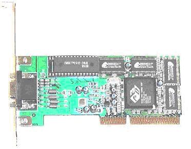
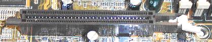
This ATI Mach64 series AGP card demonstrates clearly that the edge connector is farther back than PCI and features two rows of connectors stacked on top of each other across the card edge.
-
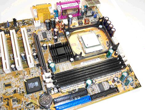
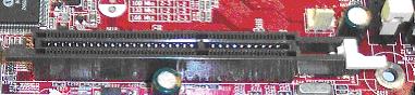
Below is a Pentium 4 motherboard with a typical AGP slot; brown in color and closest to the CPU. Note it is farther from the back of the system than the PCI slots.
-
The AGP slot was developed as the high speed video card expansion bus for the Pentium based motherboard. Only certain chipsets feature the port and quite often OEM brand PCs build an AGP video card directly into the motherboard and fail to provide an AGP slot for future expansion of the computer's video controller capabilities. Within the chipset families there was a quick evolution of AGP technology. The original slot supports 1x and 2x cards. The slot stays at a certain range of clock frequencies while the card uses a clock multiplier similar to what the CPU does with its internal clock multiplier. The chipset only needs a slight modification to accommodate video cards that clock double.
-
The AGP slot is usually brown and closest to the CPU. However there are many customized motherboards that now deviate from the standard coloration of the motherboard connectors and components so color is not the only clue to go by. Some motherboards have one or more PCI slots closer to the CPU than the AGP slot. The slot is similar in size and connector pins to a PCI slot but the divider is different and it is farther away from the back of the motherboard than a PCI slot.
Comparison of AGP slots (motherboard rear is to the left)
AGP 1.0 slot, 3.3V 1X/2X speeds (slot divider closer to rear)
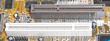
AGP 2.0 slot, 1.5V 4X/8X speeds (slot divider closer to front)
Dual function AGP slot 1.5V or 3.3V (no slot divider to block wrong card)
-
Soon a 4x slot was developed with 8x capabilities. In addition to this another enhancement called the AGP Pro slot has appeared which provides additional power pins to large power hungry video cards. These video controllers, part of the AGP 2.0 specification also run at a reduced voltage of 1.5V. Because of the different voltage requirement, the keying of the AGP slot is different from that of the AGP 1.0 specification 3.3V slots and cards that run at 1x or 2x. Unlike VESA the AGP slot connects to motherboard chipset circuitry rather than running directly to the processor pins. Because of this arbitration and the dedication of the slot to video cards the technology appears to greatly maximize the optimization of video throughput within the system which translates to vastly improved graphics since its introduction. All AGP ports are 32-bits data bus width running at 66Mhz.
AGP Port Type Voltage bits/clock Throughput AGP 3.3V 1 266MB/sec AGP 2x 3.3V 2 533MB/sec AGP 4x 1.5V 4 1066MB/sec AGP 8x 1.5V 8 2133MB/sec -
Now with the introduction of PCI-Express based motherboard chipsets, again the standard expansion bus is certainly powerful enough for the current video controllers. AGP8x slots support a throughput of 2133MB/sec which is certainly impressive, but PCI-Express supports 250MB/sec per data channel and an x16 slot has 16 data channels. While they are not sybchronous, the system can use all 16 channels to send data to the card and let the card sort the data back into proper order for display. 250MB/Sec x 16 = 4000MB/Sec. PCI-Express video controllers will continue to come down in proce and should eliminate AGP within a few years. But the VESA people may yet come up with another high speed expansion slot just for their own technologies.
-
DVI is a new interface connector for attaching video cards to display devices, usually LCD’s. Since LCD’s are digital devices, the conversion of video data into the analog Red-Green-Blue voltage scan signals is a waste since the LCD display must have the circuitry that will convert these analog signals back into digital information for use to energize the transistors that control the crystals of the LCD display. It is much more efficient to skip the conversion to analog which forces the display to basically be equipped with a set of CRT circuits to convert it back to digital again anyway. Instead the video controller can transmit the video information in a digital format directly to the display without this wasted conversion to analog and then back again. It reduces part counts as well as heat generated by the display and improves performance.
-
The maximum transfer rate of analog data by video controllers is dictated by the video RAMDAC circuitry and is roughly equivalent to the refresh rate of any analog signal driven monitor which is rather poor. Using a purely digital interface a much higher data transfer rate can be achieved which leads to much better graphics performance on screen than is possible with analog signaling. Modern monitors and video controllers are equipped with a digital interface so that the video card can transfer pure digital image data that the monitor can process internally for rendering on screen. The main standard digital interface is DVI.
-
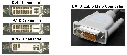
There are several different DVI interfaces. These are the three major types:
- DVI-D – DVI – Digital (Only)
- DVI-I – DVI – Integrated (Provides both digital and analog signals)
- DVI-A – DVI – Analog (Provides analog only)
The four separated pins with the cross blade pin connector are the analog section. This is the section hat sends standard RGB raster scan voltages to a CRT. The other 24-pin section of square pins carry the digital data and the Plug-N-Play interface signals.
-
3D acceleration is a reference to the developing of an image on screen in layers. In this way a background layer can be built up that can be manipulated independently of the foreground layers making scenery versus characters easier to manipulate in full screen animation applications such as video arcade style fully animated full screen games. The number of layers is usually a referred to as 16-bit, 24-bit or 32-bit Z-buffer depth. Further, the buffering can be double or triple. The greater the resolution and "flat" 2D graphics color depth the larger the flat video buffer that is required. Add to that 3D depth in which multiple 2D images are being layered on top of each other and double and triple buffered in video RAM then the more video RAM is needed.
-
2D and 3D accelerator graphics cards indicate that they support an industry standard technique for manipulating graphics. This can be either software driver acceleration which depends on the CPU to perform all pixel’s calculations or it can be hardware acceleration in which the video card includes its own graphics processing unit or GPU onboard. The GPU is a high speed specialized CPU in its own right and can receive shorthand instructions from the system rather than have the system calculate and describe each pixel which is an enormous drain on the CPU, and in fact most CPU’s simply cannot manage full screen animation.
-
Instead the system can send a command to the video graphics RAM buffer which says "Draw a circle centered at pixel 17, 109 with a radius of 78 pixels and 24-bit color of F0F000" (Yellow by the way) The GPU will handle the actual calculations of each pixel and write the values into its onboard RAM which the video RAMDAC is scanning and rendering out to the monitor. This allows the software to do more calculations concerning the game itself rather than spend the majority of the time trying to keep up with managing the colors of millions of pixels on screen.
-
The various industry standards have become more or less terms refering to their pixel resolution. They are:
- SVGA – Super Video Graphics Adapter – A pseudo-standard in which the card must adhere strictly to the published VGA standard so that all systems can boot up and display information on screen using a standard VGA text mode, after that the video controller can be switched by drivers into its native mode which can be any resolution and any method of displaying graphics to the monitor. Despite that, there are many standards above VGA listed below, and all of them are technically SVGA. SVGA is also erroneously called Ultra VGA, the term is a marketing term for SVGA cards and not a true standard.
- XGA – eXtended Graphics Array – Developed for the video controllers of the IBM PS/2 line of personal computers, close cousins to the PC, this involves aside from the low level access ports and command set a resolution of: 1024 x 768 in 256 colors or 640 x 480 in high color (16-bits per pixel = 65,536 possible colors)
- XGA-2 – An improvement on the original XGA controller allows 1024 x 768 in high color (16 bits per pixel = 65,536 colors)
- SXGA – Super eXtended Graphics Array – Adds the 1280 x 1024 resolution.
- UXGA – Ultra eXtended Graphics Array – Adds the 1600 x 1200 resolution.
- QXGA – Quantum eXtended Graphics Array – Add the 2048 x 1536 resolution.
- WXGA – Wide eXtended Graphics Array – Allows unusual sized resolutions from 1366 to 1280 pixels wide by 720 to 768 pixels high which allows it to fit the image onto an LCD screen without leaving a black unused band to the sides or above and below the used area of the LCD as other standards using standard resolutions may do.
-
Aside from the resolution of the video controller, the display device or monitor must support the resolution of the video controller or the setting in the case of controllers that support more than one resolution setting. The CGA, the first color graphics adapter of them all supported more than one resolution: 640 x 350 in 2 colors, and 320 x 200 in 4 colors. The monitor must support 640 x 350 pixels or that setting of the CGA video controller will not be displayed properly or the screen might go totally black.
-
Monitors also have a measurement called dot pitch. Dot pitch refers to the distance between the color triads on the surface of the cathode ray tube that form the different colors of the pixels themselves. The larger the number, then the farther apart these are and the poorer the quality of the image on the screen. Large dot pitch monitors are less expensive to manufacture and therefore are less expensively priced but the image on the screen is "fuzzy" while small dot pitch monitors have very crisp clear and sharp images. These however cost more.
-
The two methods of dividing the red, green and blue phosphors on the surface of the tube from each other are called a shadow mask and an aperture grill. Shadow masks lead to a higher curvature of the surface of the tube while aperture grills lead to very flat surfaces of the modern PC monitor. These were first introduced by Sony in their "Trinitron" line of televisions and these types of CRT’s were also used in the manufacture of their computer monitors as well. Aperture grills aside from being much flatter than the curved shadow mask types of CRTs have very small faintly visible lines across the screen. These are the fine wires beneath the glass surface that form the aperture grill. Even though they can be seen, the overall image quality of an aperture grill monitor is far sharper and brighter than a shadow mask type of CRT.
-
The CRT uses a single electron beam to draw the image on the surface of the tube starting at the top left corner and sweeping across the top row then swinging to the far left side it pulses across drawing the second row and so forth until it reaches the bottom of the screen. Then it swings back to the top left corner and starts again.
-
The number of times the monitor draws an entire screen of information per second is expressed as the refresh rate given in Hz – Hertz. A 60Hz refresh rate means that the monitor is refreshing the screen 60 times per second. This was the old VESA standard for the VL bus era video controllers and monitors but it causes screen flicker and is noticeable during rapid eye movements out of the corner of the eye. Look over the upper left corner of the monitor at any distant object, then sweep your eyes to the left. If the monitor has a low refresh rate you will see it flicker in the corner of your eye.
-
The reason it is clearer at the edge of your field of vision has to do with the structure of the retina and the brain’s processing of the information coming from the center of it near the focal point. The flicker is always there and always visible, your brain adjusts to it. However, the flicker does cause headaches and even triggers seizures in sufferers of epilepsy. The VESA has revised the standard and now 75Hz is the acceptable standard but there exist 85Hz and even higher capability monitors. People who suffer headaches from spending long hours working at the computer and especially people with epilepsy should consider using an active matrix LCD screen instead since each individual pixel is always on and does not get refreshed and does not therefore flicker at all.
-
The size measurement itself is questionable at best. The monitor's size is supposed to be the diagonal from top left to bottom right corner, but sometimes the "viewable portion" of this diagonal can be quite a bit smaller than the size the manufacturer claims it to be. A monitor of a particular size CRT can only handle a certain resolution in pixels. Some exceptions exist but in general these guidelines seem to hold for a majority of CRT displays in the PC industry. Typical resolutions for monitors are:
Monitor size Resolution (pixels width x height) 14" 640 x 480 15" 800 x 600 17" 1024 x 768 19" – 21" Varies from 1024 x 768 or better > 21" Dedicated to graphics, very high resolution monitor -
The color depth that a CRT supports varies greatly from one manufacturer and price range to the next. Older VGA monitors cannot be expected to handle color depth much greater than the VGA standard of 256 basic colors in the palette. Although some can handle high color. The most destructive setting for a monitor is the vertical refresh rate or the number of times per second the video controller attempts to create the entire screen image per second. Older monitors will adhere to the VGA standard of 60Hz which causes very noticeable screen flicker and should only be used on machines whose output to the screen is not depended upon heavily like servers locked away in a closet. When they are attached to a video controller that is driving a 75Hz or higher refresh rate signal the tube cannot handle it and the screen will be stretched and roll too fast to be seen. Worse, it can literally destroy the monitor’s circuitry. When connecting a new monitor to a system and the video card could possibly be set to a very high resolution in pixels, color depth, or refresh rate, start Windows in safe mode to bypass the video card drivers and leave it in the default VGA settings which will not destroy a monitor. The settings can then be checked by right clicking the desktop and choosing properties. If the settings are too high or in doubt, record the current settings and then change them down to settings that the current monitor can handle.
-
When attaching a monitor to an unknown system running Windows, how should Windows be started to avoid allowing the video controller to possibly dmamge the monitor?
-
What are the main display settings that could either distort the image beyond recognition or even damage the monitor?
-
Low vertical refresh rate can have what negative effect on the image?
-
People who suffer headaches and who work long hours at the PC should increase what setting or even change to what type of display?
-
What are the two main methods for picture tubes to divide the red/green/blue cells on the surface of the tube? Briefly describe each.
-
What feature of the monitor determines the sharpness of the image? Must this value be smaller or larger for better image quality?
-
You are considering a flat panel LCD display. It indicates that it is 2048 x 1152 and supports 32-bit color. Is this a standard aspect ratio? What video graphics mode output would the video card need to support?
-
XGA was the first standard to support what color depthin bits/pixel? What is the common name for this color depth?
-
Without considering animation or acceleration, how much video RAM is required to represent QXGA in true color?
-
List the video standards and their resolutions.
-
Which two AGP port speeds are 3.3V techologies? Which AGP port speeds are 1.5V technologies?
-
Most modern BIOSes can detect the voltage requirement for an AGP card as part of the modern standard. If it has been configured manually in the BIOS, and the current video card does not work, how can a new card be installed without risking damage to it?
-
A customer wishes to upgrade to a modern and powerful video card. With no technical papers for the system you decide to open it, remove the current AGP card and check the slot. You find that the divider is closer to the rear than to the front of the system. Can they get the new monster video card? Explain.
-
If a new system will not be running full screen animated graphics under any condition, a cheap alternative to an AGP video controller would be what?
-
What is the standard encoding for plain text in the PC?
-
What is the standard VGA/SVGA connector on the video controller?
-
A customer has an SXGA capable video card, he is trying to buy a 15" CRT display. What is the minimum size that you would recommend? Why?
-
The VGA/SVGA connection to an LCD display is inefficient because digital image data is converted into analog data sent to the display which must convert it back into digital data again. Some LCD's eliminated the Analog-to-Digital converters and receive pure digital data from the controller. What type of connector would the video controller have?
-
Define the acronym DVI. List amd describe the three types of DVI connector?
Copyright©2000-2007 Brian Robinson ALL RIGHTS RESERVED