CET1173C Network+ - Introduction to Networking
Materials: Lecture Only Lecture OnlyObjectives: The Definitions of Networking,The Major Networking Paradigms,The Physical Scopes of Networks,The Physical and Logical Topologies of Networks, andThe ISO OSI model will be Introduced.Competency: The student will understand what constitutes a network of PCs and be able to describe the major networking paradigms. The student will be able to recognize the type of a network based on its physical extent or scope. The student will be able to describe and explain the different physical and logical networking topologies and be able to describe the ISO OSI model layers and their functions. |
Lecture
In order to introduce PC networking it is necessary to define what a network (of PCs) is and with this information be able to identify a network and distinguish it from setups that look like networks but are not true functioning networks.
Definition: Network Two or more PCs that share resources intelligently.
We will define resources as hardware, software, or data. The key word in this definition is “intelligently.” By this we mean that each PC is “aware” of the other one. The first will make a request for a resource to the second one which will make a decision concerning the request and respond to it either granting or denying the request. Here is an example of two PCs that share a printer, but neither machine actively participates in this sharing; rather it is done manually by the user flipping the switch:
However, the diagram below is a network because the printer is attached to one of the PCs. And in order for the other PC to print, it must send a request to the PC to which the printer is attached. That PC must actively grant the request and receive the information to be printed then pass it on to its printer: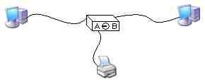

Having defined and clarified what constitutes a network and what does not form a network, we can move on to discuss the reasons for building PC networks and what is required to construct a PC network.
Here are the main reasons or benefits for networking PCs:
Sharing hardware: reduces overall cost. Any component can be shared but the most commonly shared components and peripherals include printers, optical drives, modems, scanners, and hard drives including fault tolerant RAIDs. Sharing data: makes corroboration and synchronization of information easy. Email: users no longer have to walk across the building to tell each other things. Security: files do not have to be stored on the user’s system, they can be stored on a server which will control access to the information. Remote control: help desk can monitor a user’s actions and even show them what to do across the network. Simplified backup: If the users store important data on the centralized server, then only one PC has to be backed up. Here are the basic requirements for setting up a network:
Need: It seems obvious, but if a network is not needed, then it won’t be built. Communication peripheral: On PC’s this is usually a NIC (Network Interface Card) Communication medium: With most existing networks this consists of special networking cables, but wireless networking technologies are emerging that require no physical media. Network Protocols: A common set of languages with which the machines will share information across the wires. Network Operating System (Server software): Software that enables the sharing of resources by responding to requests for access to resources. Network Operating System (Client software): Software that enables the sharing of resources by making requests for access to resources. Resources to be shared: including hardware, software and data. Now we will define and discuss the four major networking paradigms: Peer to Peer, Distributed centralized processing, Client/Server, and Centralized processing.
It is actually easier to define these starting with the last one: Centralized Processing. This is the oldest installation level network and is the model exemplified by the classic IBM mainframe to which “dumb terminals” are attached. The dumb terminal has no computing power of its own (hence the term) but simply transmits keystrokes to the main frame which transmits information to be displayed on the screen directly back to the display circuitry. All of the processing power of the network is done by a single central processing system: the IBM mainframe computer.
In the Client/Server model, a server is at the center of the network but it does not have to perform routine processing tasks such as capturing each users keystrokes and then transmit that data back to the display circuitry. The clients are PCs in this scenario and they perform the vast majority of the processing for each users daily activities. The Server only performs the function of joining all of the users PCs into a network in which it is at the center. The Server is the computer that grants or denies access to shared resources and is usually the computer that possesses the resources to be shared. All of the Client PCs request access to the resources of the Server.
Distributed Centralized Processing is an emerging hybrid technology in which each PC devotes time slices of its processing power toward a virtual server program that is running on two or more or all of the interconnected PCs in the network. There is no actual physical server in the pure “Cluster Server” model, just the virtual server program running concurrently across all of the client systems. Currently Microsoft offers dual PC Cluster Server capabilities with Windows 2000 Advanced Server but each PC is dedicated to the role. Windows 2000 Data Center Server allows for more than two PCs to be interconnected to function like a single server, but again those PCs are dedicated to generating the virtual cluster server.
In a Peer to Peer network each PC functions as both a Client and as a Server. Each PC can make requests to any other PC for resources, and each PC can grant requests of other PCs to access its resources. To this extent each PC is fairly much equal in functionality to any other system on the network hence the name Peer to Peer.
In microcomputer networks the most common paradigms that have been implemented are the Peer to Peer model and the Client/Server model. Recently Windows NT 4.0 and Windows 2000 Servers have offered the ability to function as graphical centralized processing systems serving graphical dumb terminal emulators. The Client PC runs the Graphical Terminal Client software which attaches to the server. At that point all keystrokes are sent to the server to be processed and all images on screen are transmitted back to the Client from the server. This scheme takes advantage of the server’s expensive processing capabilities if the clients are sufficiently inexpensive and do not bog the server down.
- Since the majority of networks these days are built around the Peer to Peer or the Client/Server paradigms we should compare the two in order to be able to make an intelligent choice in which solution should be chosen based on the circumstances.
Feature Client/Server Peer to Peer Access Control Precisely configurable, centrally managed at the Server Much less precise, not as concise, managed at each station Security Very High due to feature above Very Low due to feature above Performance High due to dedicated Server PC Low because each PC must perform both workstation and server tasks. Hardware Costs High due to Server hardware Low, any PC can participate Software Costs High due to special server OS Zero, built in to Windows Backup A well managed network can have backups that are easily implemented Very difficult to implement since each PC must be backed up independently. Redundancy Very good due to special server hardware and software Essentially none due to the lack of server hardware and software.
It should be noted that Peer to Peer is difficult to manage access control and therefore security is low. Such a network is only suitable in situations where security is not an issue and since it is difficult to manage and backup it is only suitable in small LANs. It is an ideal solution in those circumstances and in circumstances where the implementation should be quick and inexpensive as well. Peer to Peer networks are not scalable. You cannot start off small and then grow it to any large future size. If this is expected then the LAN should be well thought out in advance as if it already were large with just a few stations on line.
- Networks are subdivided not only by the functional paradigms described above, but also by the physical size or scope as follows:
LAN – Local Area Network. A local area network is basically limited to a single physical structure or building. Anytime a network must extend beyond the confines of a single structure special equipment must be used, and the network is no longer a LAN. MAN – Metropolitan Area Network. At least two LANs in separate buildings joined by special equipment defines a MAN. The most common hardware solutions involved in MANs are fiber optic or wireless. While expensive they are not nearly as expensive as the WAN equipment. The MAN by definition can span a county or large metropolitan area hence the name, but in this case it would probably use equipment that defines the WAN and should be categorized as such. WAN – Wide Area Network. A wide area network joins LANs that are separated by distances that exceed the capabilities of the physical layer technologies of the OSI model (as do many MANs). Due to the large distances extremely expensive equipment would have to be leased or purchased. Often third party vendors lease the special communication lines and equipment necessary to join LANs separated by significant geographical distances. WANs span cities, but two offices at opposite ends of a county will probably use a WAN solution and should be considered a WAN not a MAN. The Internet – A special single WAN that spans the entire globe and has a large and expensive backbone structure supporting it that is funded mainly by Governments. The Internet is completely heterogeneous, member systems range from single PCs attaching via dial up phone line modems to huge warehouses of IBM mainframes attached by dedicated ATM (Asynchronous Transfer Mode) lines that can handle data bursts of up to 40Gbps. The Internet features several different information exchange technologies of which HTTP (HyperText Transfer Protocol), FTP (File Transfer Protocol), and SMTP (Simple Mail Transfer Protocol) have risen to the forefront of popularity and usage with the proliferation of both web servers and web browser applications for the home user. Intranet – A private LAN, acting like the Internet. This means that the network is not actually available or accessible via the Internet, but each server (or Peer) runs a web server software package and each Client accesses the shared resources with their web browser. Extranet – The Internet acting like a private LAN. In this case the servers are available or accessible across the Internet, but when accessed they demand a Logon and will only share with authorized personnel and at that point share resources through familiar looking LAN interfaces (like “My Computer”). We should now take a look at the various network topologies. This term simply defined means the way in which each node is connected to the other nodes. You are expected to be able to recognize the four classic topologies: bus, ring, star, and mesh.
- In a bus topology all attached PCs are physically attached to the same single wire which runs from one end of the network to the other:
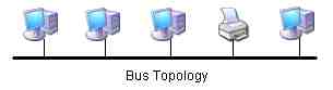
Like any bus each end of the bus line must be terminated to avoid electronic reflections off of the ends that can be mistaken for valid data bits and ruin transmission integrity. Each attachment to the bus involves a T-connector as well. We will cover the connectors and cables in depth later.
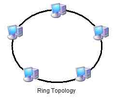
- In a ring topology each PC (or networked device) attaches to two neighbors which are referred to as the upstream neighbor and the downstream neighbor. Information arrives at the PC from the upstream neighbor and is inspected to see if the content is intended for this PC. If not the transmission is forwarded to the downstream neighbor. Information proceeds around the ring until it arrives at its intended target. The most popular ring topology implemented in PC networking was the IBM Token Ring which is no longer produced and support has dramatically fallen off. The ring topology looks like this:
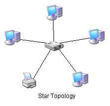
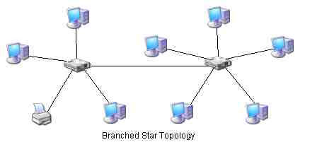
- The previous two physical topologies are rarely seen these days because the equipment is all defined by older and slower network specifications. The new high speed specifications are extensions of an older contemporary to the bus and ring topologies that used the star topology. In a star each networked PC or device attaches to a central wiring device that distributes information along each independent path to and from each networked device. This central device looks like it is at the center of a wagon wheel, each spoke of the wheel is a wire that leads out to a particular device. This places the network concentrator (the old name) at the hub of the wheel (the new name). We will discuss the various networking hardware devices later. The star network topology looks like this:
- Star topology can also branch out by replacing any one of the above networked devices with another concentrator like this:
- The last physical topology type is the mesh. In a physical mesh network each PC or networked device has an independent physical attachment to each other PC or device. Physical mesh networks are prohibitively difficult to implement due to the number of wires that would be required. Here is an example of a mesh topology:
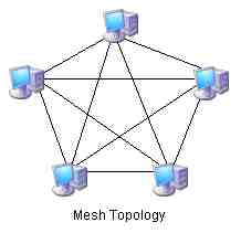
Each member PC of the 5 node mesh requires four communication devices and wires to attach to the other members of the network. This means a total of 20 network interface cards, and 10 wires (a NIC at each end) are required to network just five PCs. For six PCs this would require 30 NICs and 15 cables. The cost to add one PC to the mesh is more than that of adding 10 PCs to a bus.
Introduction the ISO OSI model. The International Standards Organization located in France insists that its name is Organisation Internationale de Normalisation. A change from the original Organisation de Standardisation Internationale. They insist that “ISO” is nothing more than a “nickname” since it is not an acronym of their initials. ISO is one of the bodies that develops papers that describe engineering standards for the PC industry. If all manufacturers adhere to an ISO paper like ISO9660 then all systems can read ISO9660 compliant CD-ROMs. The Open System Interconnection model is considered a recommendation of how an ideal network should be constructed from the physical components to the operating system links. What gave the OSI model the weight that it has now, is that the U.S. Government made the decision to only purchase networking systems that adhered to the OSI model.
- The OSI model breaks the functionality of a computer networking system down into seven distinct layers. Each layer is to function completely independently and transparently with respect to the other layers. That is, changes can be made within any layer that will have no consequence on the function of the entire stack as long as the changes do not affect the “hooks” between the layers above and below. The OSI model looks like this:
Layer What it does Application Access points into the local operating system Presentation Translates so that both systems use the same encoding scheme Session Establishes the nature of the conversation between two systems. Transport Sorts, reassembles, and error checks/corrects packets. Network Establishes Logical Network addressing for the PCs Data Link Establishes low level addressing and access to the wire. Physical The transceiver circuitry (NIC) and the wiring.
Bear in mind that the OSI model does not go into the specific implementation of any layer. It simply suggests that when a Networking technology is designed that it should be broken up into these seven layers. And that these layers should be kept discrete.
Let’s elaborate on the functions and structures involved in each layer. The physical layer is the easiest to identify but probably the most difficult to actually make since it requires manufacturing facilities. Also all of the physical equipment from the transceiver peripherals that will be installed on each PC, to the cables must all conform to very exact engineering specifications for the network to function on a variety of computers in a variety of configurations in a variety of conditions. To this end the physical components of the network are designed and built according to the most rigorous specifications of all of the OSI model’s layers.
The physical components of the network include the transceiver peripheral that will be installed on each PC; usually a Network Interface Card or NIC. The NIC must attach to other systems via cables (except in the modern wireless LAN specifications) capable of carrying the data at the frequency (speed) required by the specification. This also involves special connectors at the ends of the cable to attach to the corresponding opposite connectors on the NICs and other network hardware appliances as needed. This is all directly related to the physical topology that has been chosen for the network specification as well. In the next module we will discuss physical layer technologies and their associated hardware.
The Data link layer is the first of the six logical layers that reside on top of the physical layer. This one is significant in that it is directly bound to the physical layer. The program instruction packages at the Data Link layer are designed specifically for the physical layer and are not interchangeable from one technology to the next. As a result of this, the physical layer technologies also define their own distinct Data Link layer protocols and the two are bound together.
The functions of the Data Link layer have been broken into two major subcategories: the Logical Link Control sublayer and the Media Access Control sublayer. The Media Access Control (MAC) sublayer handles the issue of addressing. Each physical NIC attached to the network must have a unique address by which the other physical NICs can set up a transmission intended for it and no other NIC. The Logical Link Control sublayer defines the structure of the packets that it will send, and decodes packets that it receives. LLC also handles error checking and correction, flow control, and allows for connectionless communication as well as connection-oriented communication. In this LLC can throw packets out onto the wire and “hope” that they reach the intended destination (connectionless) or call for a particular PC or device specifically by its MAC address, await that unit’s response and then begin a dialog with it (connection-oriented).
The structure of the packets (series of bits, in which each bit by position in the entire transmission has a specific meaning), the nature of the error detection and correction schemes, flow control methods and session handling (connectionless vs. connection-oriented) all run along with the actual NIC control program code and define the physical technology in use. Examples of these technologies or physical network protocols are: ARCNet (Attached Resource Computer Network, obsolete), IBM Token Ring and Ethernet of which there are several types.
The Network layer establishes logical addressing for the member PCs of the network. This means that the physical NICs do not have to be able to directly transmit and receive between each other in order for the information to be exchanged. Said another way, without the Network layer, the only way that the computers could exchange information would be if there existed a direct electronic signaling path or wire between the two machine’s NICs. If not then the two machines would be unable to find each other’s MAC addresses nor be able to exchange LLC built packets. This would confine all networks to be no larger than a LAN. MANs, WANs, and the Internet itself could not exist. The Data Link layer packets carry a data payload from one physically attached device to another. That data payload can be a Network layer packet. Because of this there can be an intermediary device that is physically attached to one particular physical network (a physical segment) and also attached to another independent physical segment. This device can exchange Data Link layer packets with all devices on one physical segment and inspect the data payloads to see if there is a Network layer packet with the destination logical Network address of a device attached to the other physical segment. If this is the case, this device would then strip the network packet out of the Data Link layer packet that is recognized on the one physical segment and retransmit it in a new Data Link layer packet that will be recognized on the other physical segment. In this way the Network layer packet can be retransmitted from intermediate device to intermediate device until it arrives at the intended NIC. The information can now travel beyond the physical segment if the intermediary device is present and configured properly. These devices are called routers. Examples of Network layer protocols which handle the assembly and interpretation of the Network layer packets are: IPX (Internetwork Packet exchange – by Novell for their Netware OS) and IP (Internet Protocol – native to the Unix OS and used on the Internet).
The Transport layer works in close coordination with the Network layer protocol and is usually distributed with it. The data payload of a Network layer packet is almost always a Transport layer packet. The Network layer protocol will receive a packet intended for it and strip out the data payload and hand it up to the Transport layer. This layer handles error detection and correction along with sequencing and “piping.”
The system can be involved in more than one conversation on the network at the same time. If it is, then each application running on top of the operating system such as Internet Explorer and FTP have the same Network address (this PCs Network address) so when the packets arrive; one for Internet Explorer then one for FTP, how will they be separated and sent up to the correct application? The Transport layer handles this function called “piping” with the use of “Ports.” These ports are logical ports and have no physical manifestation like a serial port does. Instead the application attaches the desired port number to its request from the above layers and the Transport layer will construct a Transport layer packet with this number in the header. Applications are designed around the use of these ports called “well known ports” and will ask for and receive the information based on the port number.
The Transport layer also numbers the packets when a large block of data must be transmitted which does not all fit into one packet. In this case the packets are given the port identifier and the sequence number then passed independently down to the Network layer which attaches the source and target network addresses then passes the Network packet down to the Data Link layer for transmission. This series of packets travel through various routers and might have to wait while some distant physical segment is busy and can arrive at the destination out of order. The Transport layer will gather them into a location in RAM and reassemble them into their correct locations until the entire message is reassembled then pass it up to the next layers.
If one piece never arrives, the Transport layer will send down the stack a request for retransmission of the lost packet. So the Transport layer handles error detection and correction at a number of levels including the calculation of CRCs (Cyclical Redundancy Check bytes) which it embeds in the Transport layer packets and reads out of the arriving packets. Examples of Transport layer protocols are: SPX (Sequenced Packet exchange – by Novell for Netware OS) and TCP (Transmission Control Protocol – native to Unix OS and used by the Internet). Since it attaches to a particular Network layer protocol it forms the popular suites IPX/SPX for Novell Netware and TCP/IP for Unix.
The next three layers are not nearly as well defined and separated like the lower layers are. The reason for this is that the current protocol of the Internet; TCP/IP, was designed for the Department of Defense during the experimental development of the ARPANET (Advanced Research Project Agency Network) which would later be deregulated and become the Internet. The DoD model had fewer layers and essentially lumped the Application layer together with the Presentation layer and the Session layer of the OSI model. Many TCP/IP programs are stand alone programs that handle all three layers because they are older than the OSI model.
Many Session layer functions are intimately bound to the Transport layer in the TCP/IP protocol suite. The Session layer handles the dialog method and control that will be used for communication of the lower level packets. The systems can establish a connectionless communication which means there is no dialog or Session at all or they can establish one of two main types of connection-oriented communication: TWA - Two Way Alternate or TWS – Two Way Simultaneous.
TWA sessions feature a dialog control token in which the system that possesses the token has the power to transmit, and the system that does not have the dialog control token must listen to the designated Transport layer port for an incoming message from the other system. In TWS, the two systems both have the power to transmit at the same time and both are obligated to listen to the designated Transport layer ports for incoming messages from the other system. The two systems will engage in a TWS dialog even if the hardware does not specifically support full-duplex communication. In this case the two NICs will take turns transmitting and receiving data but at the Session layer level a virtual TWS Session will be maintained. In such a Session, flow control and message synchronization information is “pumped” into the dialog data packets for the Session layer protocols to monitor and maintain the TWS dialog.
The Presentation layer handles the conversion of local data encoding into data encoding that can be understood by the target PC. Without this layer in effect, connecting to an IBM mainframe would be futile since those computers do not use ASCII to store or display regular text. They use an encoding called EBCDIC (Extended Binary Coded Decimal Interchange Code). Without a Presentation layer loaded while communicating with the main frame all text including files in its native EBCDIC will look like random funny characters on screen. The Presentation layer handler will translate from EBCDIC to ASCII on the fly as the data passes through the layer.
The Application layer is the entry point of information headed to the network and the destination point for information arriving from the network. It does not mean the application itself like Internet Explorer. What it does mean is that Internet Explorer will attach to the operating system and the operating system passes information into and out of the Application layer “hooks”. So when you type in “C:\” in the address bar, Internet Explorer will request that directory information from Windows and display the result in the browser window. If you type in “Z:\” and that drive letter has been set up by the Application layer interface then the contents of some remote computer’s drive will be displayed in the Window. The local operating system passes the request to the Application layer support which then translated the request down the OSI layers out onto the wire. The responses come back up the OSI layer stacks and the information is ultimately handed back to the Application layer which then hands it to Windows who then delivers it to the Browser.
Review Questions
Write the definition of a Network:
Is a Printer A-B switch an example of a Network? Why?
List the six reasons for constructing a Network:
List and describe the four networking paradigms:
Which two paradigms are by far the most common?
Give four reasons why you would use the Client/Server paradigm over Peer to Peer:
Give four reasons why you would choose the Peer to Peer over Client/Server:
List and describe the basic requirements for constructing a network:
List and describe the six main physical scopes of networks:
List and describe the four physical topologies of networks:
Explain the difference between a physical and a logical topology with an example:
List and describe in the seven layers of the OSI model:
Ethernet is a published standard which encompasses what OSI layer(s):
What layer communicates with the operating system?
What logical layer communicates directly with the NIC?
What layer establishes direct physical segment addressing?
What is the name of the sublayer that handles this addressing?
What layer constructs and decodes the packets that are transmitted between NICs?
What is the name of the sublayer responsible for this process?
What layer manages addressing that can go beyond the physical segment?
What layer separates incoming packets and sends them to the correct application destination?
What is the name of the “pipes” used to control this?
The Internet has defined many of these so that they are normally associated with a particular protocol or application, these are called:
What layer reassembles packets into their correct sequence?
What layer handles logical error correction (like a missing packet)?
What layer handles the method of communication in a connection-oriented dialog between two systems?
Name the two dialog control methods used by this layer to coordinate a connection- oriented dialog:
Which of these is logically a half-duplex dialog?
Which of these is a logical full-duplex dialog?
What layer handles the translation between data encoding on the local system versus the data encoding of the distant system?
What layer is bound to the Network layer and is usually packaged with it?
Which three layers are the least well defined. Explain why.
Name a network paradigm that depends entirely on the power of the server.
Name the network paradigm that can feature a logical star topology, but physically all systems are Peers. How does it do this?
Name the layer that attaches hooks directly into the operating system layer and provides the access points for information to pass to and from the network:
The Session layer is bound most closely to which neighboring layer:
The NIC type is determined at which layer:
The NIC drivers correspond to which layer:
Give three examples of types of networks whose specifications encompass these two layers:
These specifications describe the methods of transmission, the design of the NICs, the cabling media and connectors which means they also specify the physical connection arrangement of the member computers this is called the:
A company wishes to link their two LANs in neighboring buildings using LAN hardware. This is an example of a:
If they used a dedicated wire leased from the telephone company this would be a:
If they used the Internet to gain access and logon to the servers this would be a:
Copyright©2000-2009 Brian Robinson ALL RIGHTS RESERVED