CET1173C Lecture #2 - Physical Layer
Materials: LectureAny demo equipment, devices, etc. LectureAny demo equipment, devices, etc.Objectives: The various physical layer components, including,The specifications of the components,The major physical layer technologies, including,the various forms of Ethernet, andIBM Token Ring.Competency: The student will become familiar with the physical layer components and technologies and be able to recognize, install and configure the various major physical layer technologies with an emphasis on LAN design, installation and configuration using the various forms of Ethernet. |
Lecture
-
The OSI model physical layer consists of the actual hardware components used to network computers. We have seen that any intelligent communicative connection between two PCs does constitute a network. So, connecting two PCs with a crossover parallel port cable and running INTERLNK.EXE on one and INTERSVR.EXE on the other will establish a rudimentary nonscalable network between the two machines. However, our discussions will now be limited to the "true" networking technologies that have been designed from the ground up to serve as networking technologies. These technologies usually involve specialized hardware as well as software packages in order to allow for far greater scalability and versatility.
-
When engineers design the physical layer equipment they must also by necessity design the signaling and encoding/decoding methods that the devices will use in order to exchange data. This directly translates into the design of the Data Link layer for that technology as well. This module will describe mainly the Physical layer. The Data Link layer will be covered in the next module.
-
We will only briefly discuss the IBM Token Ring since these installations are being replaced by Ethernet due to a lack of new equipment availability and a severe fall off in support. The IBM Token Ring is a Physical/Data Link layer technology that defines the specifications of hardware and the methods that these hardware components will use to exchange data. The IEEE (Institute of Electronic and Electrical Engineers) is the main body that publishes the official specification documentation for the various networking technologies. These are detailed recommendations to which manufacturers can adhere closely while designing equipment to ensure that their equipment will be fully operable with other manufacturers equipment intended for the same network type. In networking the concept of "open architecture" has been strictly adhered to, as a lesson learned from the success of the IBM PC.
-
The IBM Token Ring technology adheres to the IEEE 802.5 document. The original specification allowed for data transmission speeds of 4Mbps and was later amended to allow for transmission rates of 16Mbps. It should be noted that when referring to these serial transmission technologies, the "Mega" prefix is usually intended to mean exactly one million (1,000,000) and NOT a binary "Mega" (1,048,576). IBM Token Ring technology uses a completely different Media Access Control sublayer technique from Ethernet which will be covered in detail. The token ring technique is a form of media contention similar in general effect to, but no longer referred to as a form of CSMA/CA - Carrier Sense Multiple Access with Collision Avoidance.
-
The concept of networking computers involves an issue very similar to what motherboard designers faced in the very beginning. The problem of multiple devices responding to asynchronous triggers (arriving data across the phone line and your finger tips at the keyboard) and contending for the processor simultaneously. The solution on the internal bus of the computer was the PIC (Programmable Interrupt Controller). This arrangement most closely resembles a star in which each device has an independent IRQ control line that enters the IRQ controller which then stores the requests and makes priority decisions and presents them one at a time to the CPU.
-
With a network, the same situation exists. Multiple computers have access to the cable and the ability to initiate transmission at any time. This transmission can reach any other computer unlike the IRQs which travel directly to the PIC which is designed to control them. This situation means that collisions are to be expected and a recovery process must be designed. In the IBM Token Ring the possibility of a collision is removed by attaching the computers in a physical wiring ring. At any moment any PC could begin transmitting but that transmission does not go onto a cable shared by all of the other PCs. It enters onto a cable that is attached to the Nearest Downstream Neighbor only.
-
Furthermore, at the Media Access Control sublayer of the Data Link layer, the control programs of the token ring network interface card only allow it to initiate transmissions if the program has received a special transmission packet from the Nearest Active Upstream Neighbor (NAUN) referred to as a Token, hence the name of the technology. If the MAC sublayer does not have the Token then all it can do is listen to the NAUN. If a packet arrives the NIC drivers must interpret the contents and determine if the packet is intended for this PC. If so it will be copied into RAM and also forward it around the ring to the Nearest Downstream Neighbor. The packet will continue around the Ring until it arrives back at the PC that originally sent it. That PC will then remove the packet and read it to see if the destination machine modified the acknowledgment field.
-
IBM Token Ring networks do not appear to be wired as physical rings. Each computer does not have two cables attached to it, one running from the NAUN and another running to the Nearest Downstream Neighbor. Instead each PC has a single cable that attaches to a device that resembles a hub. Physically the cabling of the installation looks like a star topology.
-
However, the physical functionality of the network is that of a ring. The physical ring exists entirely within the hub-like device called a MAU or MSAU (MultiStation Access Unit). Internally the MAU switches open cable pathways from computer to computer effectively making the arrangement a physical ring. MAUs can also be cascaded expanding the ring.
-
On heavily populated LANs the 16Mbps IBM Token Ring has been known to perform as well as a 100Mbps Ethernet system. This is due to the escalating number of collisions that can occur on a busy Ethernet LAN, which is designed around the paradigm of CSMA/CD: Collision Detection (collisions are expected and dealt with).
-
Before introducing Ethernet let us look at the physical components of a network. The PC must possess a network transceiver peripheral device. This type of expansion card is referred to as a NIC (Network Interface Card). Most NICs are internal though with new high speed external expansion technologies like USB, external NICs have arrived on the market. USB 1.1 has a high channel speed of 12Mbps which makes it suitable for the 10Mbps Ethernet technologies but not for the 100Mbps Ethernet. USB 2.0 has a 480Mbps transmission rate and can handle 100Mbps Ethernet. Internal cards are either ISA which means that the card's resources must be configured manually, or PCI in which the card can automatically negotiate resource allocation with the PCI bus arbiter.
-
The ISA bus maximum transfer rate is 16.66MB/sec, but this is an ideal theoretical value that the bus never actually attains because it is asynchronous in nature. This equals 133Mbps which in theory is fast enough for 100Mbps Ethernet but the bus can never actually achieve and certainly cannot maintain this transmission rate. If it did all other devices would be locked out of the bus for unacceptable periods of time. 100Mbps NICs appear to all be PCI expansion cards. The PCI bus has a throughput of 133MB/sec which equals 1064Mbps which is more than sufficient for 100Mbps Ethernet cards.
-
The internal NIC must successfully negotiate or be properly configured to use standard expansion card resources including IRQ, DMA, I/O addresses and if necessary memory addresses. NICs rarely use a DMA channel although there is no reason to assume that a particular card does not use one. In the case of an ISA card it may be necessary to determine which resources are available and then manually set the resources that the card will use with jumpers and/or dip switches. Some late model ISA cards are software configurable and must be set using a configuration utility that comes in the package with the card. This step is done prior to the installation of the drivers and often requires a reboot of the system before the settings actually take effect.
-
Some older PCI cards must also be configured with a utility although this fact makes the card non-PnP compliant and it is therefore not a true PCI device. This means that the card should be expected to cause problems at some point on the system. Otherwise the true PCI card should be able to automatically negotiate resources either with the PCI bus arbitrator or the system can leave the card with no resources assigned to it until the OS loads. The drivers can then assign resources and initialize the card.
-
In the case of the 3COM 3C905 TX cards installed on the classroom systems, these cards come with configuration software that can be used in the case where a non-PnP OS will be used such as DOS, older versions of Novell Netware or older versions of Windows NT. Once configured by the utility the drivers can be loaded for these operating systems and the card will be accessible and function. The OS will be unaware that it is a PnP device attached to the PCI bus. Included with the card's drivers and the configuration utility is a testing program. In the case of the 3C905 cards the configuration utility is also the program that can test the cards for functionality. In order to test the cards pairs of cards can be attached using a crossover cable.
-
Create a bootable diskette and copy the configuration program to it. Also copy the DOS client drivers for Novell bindery services connectivity (Netware 3.12) to the diskette. Copy the memory manager, and CD-ROM support drivers to the diskette.
-
Create the CONFIG.SYS and AUTOEXEC.BAT files that will offer a menu with the functional choices of: Load No drivers, load CD-ROM support, Load Network drivers only, Load all drivers (Network and CD-ROM support). (This operation will be performed in the classroom)
-
Each student will be issued two cables, a straight-through cable and a cross-over cable. The straight-through cable is intended to connect the NIC to the network connectivity device and the cross-over cable is wired so that the transmit wires of one connector attach to the receive wires of the opposite end connector. This allows the cable to directly connect two NIC's to interchange information without the need of any intermediate networking device like a hub. Select the cross-over cable and attach it to the expansion card NIC at the back of the system and attach the other end to the expansion card NIC of your neighbor's system.
-
Boot each PC and enter the BIOS. Be sure that the BIOS is set to "PnP OS installed = No." Proceed to boot with the NIC driver diskette and load no drivers. Attach the crossover wired UTP cable to the NIC at one end and to a neighbor's NIC at the other end. Run the configuration program. Allow the utility to Autoconfigure the card then run the individual NIC card tests. Interrupt the test after a few successful repeats and then run the Echo server tests. Both cards should pass all tests including this last one in which the cards successfully exchange test packets. Once complete change the cross-over cable for your neighbor's cable and make sure that the NICs can exchange packets through it as well. View and record the NIC's Information and Stats.
-
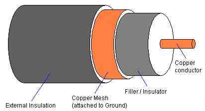
Each technology defines the connectors and cabling types that should be used in order to be able to carry the signals from computer to computer without data loss. Some systems employ coaxial cable which is constructed like this:
-
Signals travel as voltages on the central conductor which is surrounded by a layer of polyurethane filler/insulator that serves to separate the conductor from the ground line and to give the cable shape and stiffness. The copper mesh is wrapped around the filler and is attached to ground at one end; never both as this will form its own circuit called a "ground loop" which will paralyze the bus activity on the central connector. This is protected by an outer coating of insulator usually made of PVC. Coaxial cable takes advantage of the laws of electromagnetic energy field propagation. By measuring the distance between the center wire and applying a field effect formula expressing the relationship between the voltages that the center wire will carry, the mesh can be positioned so that electromagnetic field effect caused by the traveling voltages in the center wire will not extend beyond the copper mesh layer. Conversely no external electromagnetic fields will interfere with the central wire either. This is in theory. A strong enough external field will compromise signal integrity but it would have to be substantial.
-
Coaxial RG-58 cable installations use BNC connectors as the standard connector for attaching the cables to devices. Since the coaxial cable is the basis for a bus physical topology each computer must "tap" into the bus and not interrupt it. This is done with "T" connectors. Two pieces of coaxial cable can be joined using a BNC coupler and the bus must be terminated with 50Ω resistors which also have BNC connectors on them. Here are some examples of these cabling components:
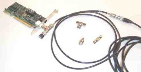
The NIC is attached to a T-connector into which the cable is plugged. The black knob on the other connector of the T is a terminator. The other end of that cable is attached to another cable with a coupler. In the middle of the loop of cable there is a T-connector at the top, another model of terminator below it and a coupler to the terminator's right. Instead of the coupler you could attach a T-connector and plug in another NIC. The physical segment of the bus continues in this way until you reach each end to which a terminator must be attached. The line must stretch unbroken and unbranched from end to end.
-
The two most common forms of coaxial cable used in the PC networking technologies were both Ethernet specifications. RG-8, also known as "thicknet" conforms to the 10Base5 section of the Ethernet specification. This cable is both thick (10mm in diameter) and quite rigid due to the fact that it is physically thick and the central conductor is a solid copper wire, making it fairly difficult to work with when a sharp corner must be negotiated. Signal integrity was however maintained for distances of up to 500 Meters (over 1,500 feet) making it ideal for large network installations that must span large buildings. RG-8 cables feature N connectors, which are screw on connectors with a center tap pin protruding out of the middle and are similar in appearance to cable TV connectors only larger.
-
The other type of coaxial cable used commonly in LANs was RG-58 or "thinnet." This cable is much thinner (5mm in diameter) and is quite flexible not only because is it thinner but also because the central conductor is a bundle of very fine copper filaments called "stranded copper wire." This makes it much more suitable for areas where sharp turns must be negotiated. This cable can maintain integrity according to the 10Base2 section of the Ethernet specification for up to 185 Meters or around 600 feet. Both of these Ethernet technologies use the coaxial cables in a physical bus topology. The picture above is all RG-58 equipment.
-
Thicknet was usually used to span large distances and usually ran through the plenum area between floors of buildings. When it passed over the location of a PC that needed to be attached to the network, a hole would be carefully drilled into the cable sheath and a "vampire tap" would be screwed onto the cable. This clamp-like device had a metal tooth that was inserted into the drilled hole and made contact with the center conductor of the cable effectively branching a connection onto the bus. The vampire tap quite often also includes the actual Ethernet transceiver circuitry as well as the coaxial core tap. In this case the transceiver unit will be attached with a cable with standard male DB15 connectors at the opposite end that connect to the NIC on the PC. The DB15 female connector on the NIC is referred to as an AUI (Attachment Unit Interface) connector and is intended for use with a vampire tap/Ethernet transceiver unit to attach the system to an RG-8 cable. The cable that runs from the vampire tap to the card is referred to as a drop line. According to the Ethernet 10Base5 committee AUI drop lines can be up to 50M in length. The RG-8 cable spanning large distances in the plenums and walls became known as the network backbone. These terms are still used even though the RG-8 cable and the AUI drop cables are no longer used.
-
In RG-58 cable thinnet systems, the cable might run around baseboards or through the partitions of cubicles so that it can reach each workstation directly since the cable is much more flexible. Each station attaches directly to the RG-58 bus cable with a T-connector as illustrated above. RG-58 cables feature a 50Ω impendence meaning that cable must be terminated with a 50Ω resistor to compensate for this and eliminate electronic reflections off of the ends of the cables.
-
The other cable type that has taken over the networking industry is Unshielded Twisted Pair, UTP. This cable is rated based on the number of twists per foot in the wire pairs within it. Standard Category 3 UTP cable was used by the original Ethernet specification and features 3 twists of the wire pairs per foot. However, by increasing the number of twists, the cable can carry faster signals (higher frequencies) without the moving electrons causing magnetic fields that distort signals in the other twisted pairs in the cable. Standard Category 5 UTP features four twists per inch, the necessary modification to allow the cable to carry data at ten times the speed (100Mbps) as Cat 3 (10Mbps). Category 5e is Cat 5 enhanced and must certainly have more twists. Cat 6 was recently ratified by ISO and must have even more twists and is approved for GigEther (1000Mbps).
-
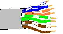
UTP cable features 4 pairs of wires. Each pair is twisted together through the main external cable sheath, which is usually made out of PVC. The pinouts are as follows:
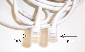
Pin # Wire Color Function Crossover Connection 1 Orange/White Transmit 3 2 Solid Orange Transmit 6 3 Green/White Receive 1 4 Solid Blue Unused 4, Unchanged 5 Blue/White Unused 5, Unchanged 6 Solid Green Receive 2 7 Brown/White Unused 7, Unchanged 8 Brown Unused 8, Unchanged The orientation of the pins on the RJ-45 connector are determined by pointing the connector towards yourself with the lock tab facing down. Pin 1 is the farthest to the right and pin 8 is the farthest to the left:
-
The section of the Ethernet specification that discusses UTP is referred to as 10BaseT. A single cable segment may not exceed 100 Meters. UTP cable is a bundle of small individually insulated wires. Each wire is usually 24 gauge AWG and insulated by a thin layer of PVC. To splice UTP requires the removal of the outer sheath of PVC and then the removal of the insulation on each of the eight internal wires. In doing this, conductor pairs often have to be untwisted in Cat5 or higher rated UTP. This effectively destroys its CAT5 rating and it is far more reliable and cost effective to simply purchase complete CAT5 patch cables slightly longer than the measured lengths that are needed rather than fool with it and ruin its high end performance rating. UTP is often reinforced with Kevlar strands running parallel through the sheath with the wire pairs. This cable is used in networks that will feature repeating devices including hubs or MAUs and is therefore seen in Star and Ring topologies although IBM Token Ring supports longer cable runs and numbers of stations on a ring when using STP or Shielded Twisted Pair which wraps the four pairs in metal foil and then wraps that with the outer sheath. STP can be used in Ethernet networks since it is far more reliable but it is quite expensive and so is rarely seen in large networks where the cabling infrastructure is already expensive enough.
-
The transmissions that we are referring to are the rising and falling of voltages on a single long cable that represent binary one's (voltage), and zero's (no voltage). Signaling of this kind is referred to as baseband communication. The cable has only one signal channel upon which data can travel directly related to the voltage levels in the cable. There is another type of communication through a cable called broadband. In broadband more than one data stream can flow through the cable at the same time. This is because the data rides within a radio frequency sine wave or carrier wave. The transmitter and receiver are tuned so that they will only read the data out of the current flow waves of a specific frequency and will ignore all of the others occurring in the wire simultaneously. If you have ever changed the channel of a cable TV you have watched broadband in action. All of the cable TV networks television channels are traveling through a single wire using broadband technology. Ethernet is a set of baseband technologies.
-
The specific encoding used by the hardware circuitry of an Ethernet NIC to transmit the information between each other on the cable is referred to as Manchester Encoding. In this encoding technique timing or synchronization is established by the digital data itself and the individual binary information bits are encoded by the changes in the voltage, not the level of the voltage. Where typically we think of a wire carrying binary data does this by saying that if it has no voltage that is a "0", and if it has voltage that is a "1" Manchester encoding says "If the voltages drops sharply within the time slice of the bit, that is a "0", if the voltage rises sharply in the time slice of the bit, that is a "1."
-
The specific document that defined Ethernet at the Logical Link Control layer was the IEEE 802.2. This however, functions only as a part of the Ethernet specification. The physical layer (cabling, signaling, etc) and the MAC - Media Access Control - layer, which is Ethernet itself, is fully laid out in the IEEE 802.3 document. This describes the technology at the engineering level defining impedance and signal attenuation in the cables, as well as all aspects of the technology including the MAC layer rules of contention for handling traffic called CSMA/CD – Carrier Sense/Multiple Access with Collision Detection. These CSMA/CD MAC layer rules are Ethernet much more so than the physical technologies that carry it between stations.
-
The IEEE 802.3 document also describes 10Base5, 10Base2, and 10BaseT. The prefix 10 means that the technology will communicate at 10Mbps. The word Base indicates that it is a Baseband technology. The 5 indicates that 10Base5 has a maximum single cable length of 500 Meters (thicknet). The 2 means that 10Base2 supports a maximum cable length of 185 Meters or roughly 200M (thinnet), and the T means that 10BaseT will use unshielded twisted pair cables.
-
In Ethernet of any type, the main issue in the design and implementation of the network is the concept of the collision domain. Since signaling collisions do occur, it is important to understand how they occur and how the system deals with them. Our discussion will begin with a 10Base5 collision domain.
-
This network is a bus in which all PC's NIC's are physically connected to the same stretch of RG-8 cable. Since each PC is an independent system it may choose to transmit a packet at any moment, if two systems initiate transmission at the same time a signal collision will occur that will garble both transmissions. Ethernet cards therefore are designed at the circuitry level to do the following:
Carrier Sense – The NIC will listen to the cable first. If the cable is "quiet" then it will immediately begin to transmit. If it is busy, then it will continue to monitor the cable until it becomes available, then begin to transmit. NICs can only actually detect a collision when it occurs to the packet that they are in the process of transmitting, passive cards waiting for the media to become available 1) are not designed to detect the collision, 2) could do nothing about it if they did (they cannot transmit a signal to the other cards because two cards are already jamming each other on the cable as it is). This feature of the NIC is called Listen While Talking – LWT. Once a collision is detected this means that at least two NICs are transmitting simultaneously. The NIC will immediately cease transmission and transmit a jamming signal; this is intended to make sure that the other NIC will detect the collision as well. The NIC will now enter a "backoff" mode. It will wait a short random period of time, calculated using the binary exponential backoff algorithm, and then attempt to transmit again. The assumption is that since the wait to retry time period is randomly counted that one NIC will attempt a retry before the other, the other will detect the activity in the line and suspend transmission due to the carrier sense feature above. In the event that the card is involved in another collision upon retry (it may not be with the same card as the first collision!), it will send the jam signal, and wait another random backoff period. Each of these backoffs is calculated using a doubling variable. The different Ethernets specify 10 to 16 retries before reporting the packet undeliverable to the upper layers. -
One of the main features that control the maximum physical size of the entire network is the signal propagation delay across the span of the network. Restated, how long does it take a signal to travel from one NIC at one end of the RG-8 cable to a NIC at the opposite end of the cable? This time delay will affect the ability of the two NICs to detect collisions and take the appropriate actions.
-
If the smallest possible Ethernet packet were a single bit in size, then the entire transmission would last for 1/10,000,000th of a second (10,000,000 bits per second). The speed of electrons through copper wire is approximately 2/3 the speed of light through vacuum or 200,000Km/sec. Multiplying these two values together (after converting to the same units of distance: 200,000,000M/sec X 1/10,000,000th sec = 20M. This means that NICs farther than 20M apart would never know that a collision had occurred. Ethernet specifies a minimum transmission size of 64 bytes of data or 512 bits although an Ethernet LLC frame will not actually be smaller than 72 bytes. Frames smaller than this are illegal and called "runts." The largest possible frame is 1518 bytes or 12,144 bits. If a single transmission on the medium exceeds this, this is also illegal and the transmitter is said to be "jabbering." This block of data is called a frame and contains specifically located fields that carry specific information about it. These Ethernet frames are constructed by the LLC sublayer of the Data Link layer programs running on the system.
-
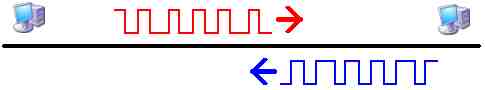
The network must be constructed so that the farthest transceivers cannot possibly transmit an entire frame to completion and then stop transmitting before a collision. To illustrate:
-
In this network the PC's are too far apart. The one on the left has completed the transmission of an entire red frame and is no longer capable of even detecting the collision that is about to occur. The transmitting PC is about to finish its blue transmission and will not be listening by the time the garbled red packet arrives and will not be able to tell that a collision occurred either. Neither system will know what happened or why the packets that they each receive are full of errors.
-
Therefore the farthest points on the network cannot exceed, half the size of a frame. So that half way through the frame transmission, the leading edge of the waves will be at the midpoint of the wire where a collision would occur and be able to reach the transmitting device while it is still transmitting the current and now damaged frame. Multiplying half of the 512 bit minimum sized packet by the length of a bit (20M) yields a maximum theoretical distance of 5120M. However, there is much more to the story than can be dealt with here. There is the problem of the resistance of the cable which causes a phenomenon known as voltage drop or signal attenuation. Some cables are better than others at dealing with this problem. Another problem is distortion or noise. Each bit is in actuality trillions of electrons crashing through the outer electronic shells of trillions of metal atoms in the wire. The farther the distance that this group of electrons has to travel the more of them will take longer routes through the metal and fall out of phase with the pulse, some will shoot through easy pathways, others will meander about through long twisted pathways and others will get completely lost along the way (resistance). This is all unavoidable but it can be controlled to a limited extent by the quality of the copper cable. Its tendency to "blur" the cloud of electrons traveling through it that represent the data is one of the causes of noise as well as outside electromagnetic waves and fields that also distort the transmission.
-
Each type of cable has a specific capacity for carrying the signal in tact over a maximum distance before it becomes too garbled to be considered reliable. For RG-8 this is 500M. For RG-58 this is 185M and for UTP this is 100M.
-
At the physical layer there are devices that can receive the attenuated and distorted signal and therefore effectively rectify the signal by rebroadcasting it down another stretch of cable. The most common of these in earlier Ethernet networks was called a repeater. This is a pure physical layer device that simply rectifies the signals reaching it and rebroadcasts them down the opposite cable with no regard to the information within the signals. When connected to RB-8 cables they can in theory carry the collision domain to a size where the minimum packet could fit onto the cables and the collision domain would be incapable of functioning. The IEEE 802.3 specification for 10Base5 Ethernet networks indicates that the collision domain can never exceed a maximum physical segment length of 2500M or roughly half the maximum theoretical distance calculated above.
-
Once a collision has been detected the detecting system must transmit the jamming signal, which is 48 bits long, then cease transmission. The recovery time between transmissions is a window into which 96 bits would fit: no transmitter should initiate transmissions during this period after a frame has ended. This recovery time window shrinks when physical devices are placed onto the cable that introduce delays in the propagation of the transmission, which repeater circuits do. It is this shrinking recovery time window more than anything else that dictates the infamous 5-4-3 Rule.
-
The Ethernet 5-4-3 Rule for 10Base5 networks states that the largest collision domain possible can be constructed using 5 physical segments of cable (500M each) connected by 4 repeaters, but populated segments must be separated by unpopulated segments to cut down on intersegment collisions.
-
The minimum separation between the physical connections of the systems to the RG-8 backbone is 2.5M. RB-8 cable was usually made a bright and distinctive yellow color marked with black bands every 2.5 meters indicating exactly where a tap could be made into it without tapping into it within the minimum 2.5M separation distance requirement for transceivers. This is to prevent the signals from being so close that a simultaneous broadcast by both transmitters would be in wave phase with each other and be very difficult to detect. Since a wavelength is roughly 20M then the rule implies that if transceivers are close to 1/10th of a wavelength apart then their waves will be in phase and inseparable from each other.
-
The maximum number of transceivers allowed on the entire Ethernet collision domain is 1024. However, if the minimum separation between station attachments is strictly obeyed it can be seen that on any of the 3 populated segments (the 3 in the 5-4-3 rule, the 4 means maximum of 4 repeater devices and the 5 of course means a maximum of 5 physical cable segments) 500 ÷ 2.5 = 200. Therefore the theoretical maximum number of stations that can be attached to this network would be 200 stations on each of the three populated segments. In practice the specification allows a maximum of 100 nodes per segment of a 10Base5 network allowing for a maximum of 300 nodes in the network.
-
The efficiency of the network dramatically declines as the number of stations increases. Increasing the average distance between the stations also negatively affects the performance of the collision domain as well.
-
10Base2 also allows the 5-4-3 Rule but each cable segment is limited to 185M. Multiply this by 5 = 925M total length of the collision domain. Here the issue is not the time delay of propagation of signals but the signal attenuation and noise. Again a minimum 2.5M separation limit between T-connectors would be expected and each segment can have a maximum of 30 nodes allowing for a total of 90 on the entire collision domain. This limit is again related to the quality of the cable and not the capacity of the Ethernet CSMA/CD rules.
-
10BaseT networks function fundamentally differently from the other two. Instead of RG-8 or RG-58 coaxial cable, Unshielded Twisted Pair category 3 or better cable is used instead. Since the conductors are far thinner and the noise is handled by twisting the conductors rather than shielding them within the grounded conductor, 10Mhz signals undergo too much loss beyond 100M to be acceptable for the specification. Also the nodes are not attached to this cable in bus fashion but rather each cable attaches to a central interconnectivity device at one end and to a single NIC at the other end. The interconnectivity device is responsible for providing the cicuitry to propagate the signal to other nodes. In the early days this device was referred to as a concentrator, but the term hub has become far more common. The stretch of cable that runs from the hub to the NIC is by definition a single segment of the network and it can only be populated by a single node unlike the population situation of the bus cables just discussed above. The hub and the NIC each always provide permanent automatic termination of the eight wires within the cable which by the way require 100Ω termination.
-
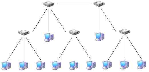
A hub through circuitry emulates the bus by broadcasting a signal that it is receiving on one port out all of the other ports. It can be thought of therefore as a multiport repeater. The hub's circuitry introduces a signal propagation delay which will affect the maximum functional size of the collision domain. 10BaseT can use the 5-4-3 rule in which 4 hubs are used instead of repeaters but the populated part of the rule does not apply:
-
The main rule to remember in 10BaseT collision domains is that if a signal has two different pathways that it can take through the hubs it will take both paths and cause problems. This must be avoided.
-
Looking at the PC on the bottom left of the illustration above, the first segment is the 100M wire that runs up to the first hub to which it is connected. This hub is connected by another 100M segment of UTP cable to the upper left hub. This is the second of the five segments. That hub is attached by a 100M cable to the upper right hub: third segment and third device. This is attached by the fourth 100M segment to the lower right hub, the fourth device. This is attached by the fifth 100M segment to the PC at the lower right corner of the picture. The signal can only travel along this one pathway between the two systems and it travels across five segments of cable through 4 devices. The reason the population rule does not apply is because there can be only a single system attached to each 100M segment. The PC at one end and the hub at the other.
-
The 10BaseT network could in practice have 1024 units if the hubs had enough ports to accommodate them, but the collision domain would get seriously bogged down.
-
One last note about Ethernet: in applying the 5-4-3 Rule, segment types can be mixed if the repeaters or adaptors are built for it. That is, a system can attach to a hub using UTP cable. The hub can have a BNC connector and attach to a 185M stretch of RG-58 (which must remain unpopulated and obey the –3 part of the rule) which attaches to a repeater with an N connector for an RG-8 500M run of cable that is populated and ends in another such repeater which attaches to another unpopulated run of 185M of RG-58 which connects to a hub which has a PC attached by a 100M UTP cable.
-
IEEE 802.2 was superceded by the IEEE 802.3 specification which has separate subcommittees for 10Base5, 10Base2, 10BaseT, several 10Base fiber optic technologies as well as the 100Base technologies and the new Gigether and 10G Ethernet which is currently under development.
-
The 100Base technologies use a frequency of 100Mhz and must have a collision domain 1/10th the size of a 10BaseX collision domain. It should also be noted that none of the original cabling used in the 10Base technologies will carry 100Mhz signals without dramatic noise and attenuation loss over very short distances. The minimum cable that can be tried with 100BaseTX is Category 5 UTP although the network is out of specification in this case since Cat5e or better is specified in the IEEE specification.
-
100BaseTX does not obey the 5-4-3 Rule at all. The maximum size of the collision domain is 205M from node attachment to node attachment. Furthermore, a maximum of two Class II (high speed) repeaters is permitted between the nodes. If two repeaters are used, the maximum distance between the two is 5M. This is to allow for Cat5e patch panel connectivity.
Copyright©2000-2009 Brian Robinson ALL RIGHTS RESERVED