CET2176C Lecture #9B - Server Networking Hardware #1
Materials: Lecture Only Lecture OnlyObjectives: The various network physical layer components, including,The specifications of the components,The major physical layer technologies, including,The various forms of Ethernet, andThe Server applications including the server physical framework.Competency: The student will become familiar with the netwprk physical layer components and technologies and be able to recognize, install and configure the various major physical layer technologies on PC-based servers with an emphasis on LAN design, installation and configuration using the various forms of Ethernet. |
Lecture
-
The OSI model physical layer consists of the actual hardware components used to network computers. We have seen that any intelligent communicative connection between two PCs does constitute a network. So, connecting two PCs with a crossover parallel port cable and running INTERLNK.EXE on one and INTERSVR.EXE on the other will establish a rudimentary nonscalable network between the two machines. However, our discussions will now be limited to the "true" networking technologies that have been designed from the ground up to serve as networking technologies. These technologies usually involve specialized hardware as well as software packages or protocols in order to allow for far greater scalability and versatility.
-
When engineers design the physical layer equipment they must also by necessity design the signaling and encoding/decoding methods that the devices will use in order to exchange data. This directly translates into the design of the Data Link layer for that technology as well. This module will describe mainly the Physical layer technologies with an emphasis on networking hardware for the PC and specifically for PC-based network servers.
-
The concept of networking computers involves an issue very similar to what motherboard designers faced in the very beginning. The problem of multiple devices responding to asynchronous trigger events (arriving data across the phone line and your finger tips at the keyboard for motherboard designers and two different nodes beginning to transmit at the same time for network designers) and contending for control simultaneously. The solution on the internal bus of the computer was the PIC - Programmable Interrupt Controller chip. This arrangement most closely resembles a physical star in which each device has an independent IRQ control line that enters the IRQ controller which then stores the requests and makes priority decisions and presents them one at a time to the CPU. There was such a network technology based on a "demand-priority protocol" called 100VG-AnyLAN based on the IEEE 802.12 document, now obsolete for all practical purposes.
-
With a network, the same situation exists. Multiple computers have access to the cable and the ability to initiate transmission at any time. However, this transmission can reach any other computer quite unlike the IRQ's which travel directly to the PIC which is designed to control them. This situation means that collisions are to be expected and a recovery process must be developed. In the IBM Token Ring the possibility of a collision is removed by attaching the computers in a physical wiring ring. At any moment any PC could begin transmitting but that transmission does not go onto a cable shared by all of the other PCs. It enters onto a cable that is attached to the Nearest Downstream Neighbor only.
-
Furthermore, at the Media Access Control sublayer of the Data Link layer, the control programs of the token ring network interface card only allow it to initiate transmissions if the program has received a special transmission packet from the Nearest Active Upstream Neighbor (NAUN) referred to as a Token, hence the name of the technology. If the MAC sublayer does not have the Token then all it can do is listen to the NAUN. If a packet arrives the NIC drivers must interpret the contents and determine if the packet is intended for this PC. If so it will be copied into RAM and also forwarded to the Nearest Downstream Neighbor. The packet will continue around the Ring until it arrives back at the PC that originally sent it. That PC will then remove the packet and read it to see if the destination machine modified the acknowledgment field.
-
IBM Token Ring networks do not appear to be wired as physical rings. Each computer does not have two cables attached to it, one running from the NAUN and another running to the Nearest Downstream Neighbor. Instead each PC has a single cable that attaches to a device that resembles a hub. Physically the cabling of the installation looks like a star topology.
-
However, the physical functionality of the network is that of a ring. The physical ring exists entirely within the hub-like device called a MAU or MSAU (MultiStation Access Unit). Internally the MAU switches open cable pathways from computer to computer effectively making the arrangement a physical ring. MAUs can also be cascaded expanding the ring.
-
On heavily populated LANs the 16Mbps IBM Token Ring has been known to perform as well as a 100Mbps Ethernet system. This is due to the escalating number of collisions that can occur on a busy Ethernet LAN, which is designed around the paradigm of CSMA/CD - Carrier Sense, Multiple Access with Collision Detection (collisions are expected and dealt with).
-
Before introducing Ethernet let us look at the physical components of a network:
- Network Transceiver: Device that actually physically transmits and receives information in a specific form. The transceiver determines the media and the transmission signaling method(s) used as well as the connectors for the media if any.
- Network Media: In the case of physical cables manufactured to carry the signals reliably from one transceiver to another and must have compatible connectors so it can be attached to the transceivers.
- Network connectivity device(s): While network technologies only require host/node transceivers and media, others require additional attachment/interconnectivity devices such as the hub or switch used in 10/100/1000BaseT Ethernet networks.
-
The PC must possess a network transceiver peripheral device. This type of expansion card is referred to as a NIC - Network Interface Card (or Controller). Most NIC's are internal though with new high speed external expansion technologies like USB, external NIC's have arrived on the market. USB 1.1 has a high channel speed of 12Mbps which makes it suitable for the 10Mbps Ethernet technologies but not for the 100Mbps Ethernet. USB 2.0 has a 480Mbps transmission rate and can easily handle 100Mbps Ethernet although it will not be sufficient to support 1000BaseT which has a maximum DTR of 125MB/sec. Also, lest it be forgotten, external expansion ports and devices represent a clear and definite security flaw in the design of the server. Internal cards are either ISA which means that the card's resources must be configured manually, or a variation of the PCI family of expansion buses in which the card can automatically negotiate resource allocation with the PCI bus arbiter.
-
The ISA bus maximum transfer rate is 8.33MB/sec, but this is an ideal theoretical value that the bus never actually attains because it is asynchronous in nature. This equals 66Mbps which in theory is fast enough for 10Mbps Ethernet but the bus can never achieve the transmission rates of modern network technologies. 100Mbps NIC's appear to all be PCI bus family expansion cards. The standard PCI bus has a reliable (synchronous) throughput of 133MB/sec which equals 1064Mbps which is more than sufficient for 100Mbps Ethernet cards.
-
The internal NIC must successfully negotiate or be properly configured to use standard expansion card resources including IRQ, DMA, I/O addresses and if necessary memory addresses. NIC's rarely use a DMA channel although there is no reason to assume that a particular card does not use one. In the case of an ISA card it may be necessary to determine which resources are available and then manually set the resources that the card will use with jumpers and/or dip switches. Some late model ISA cards are software configurable and must be setup using a configuration utility that comes in the package with the card. This step is done prior to the installation of the drivers and often requires a reboot of the system before the settings actually take effect.
-
Some older PCI cards must also be configured with a utility although this fact makes the card non-PnP compliant and it is therefore not a true PCI device. This means that the card should be expected to cause problems at some point on the system. Otherwise the true PCI card should be able to automatically negotiate all resources it needs either with the PCI bus arbitrator during the POST process (for systems with the CMOS setting "Plag-n-Play OS = No") or the system can leave the card with no resources assigned to it until the OS loads (for systems with the CMOS setting "Plag-n-Play OS = Yes"). The drivers can then assign resources and initialize the card.
-
In the case of the 3COM 3C905 TX cards installed on the classroom systems, these cards come with configuration software that can be used in the case where a non-PnP OS will be used such as DOS, older versions of Novell Netware or older versions of Windows NT. They will however work completely properly whether the configuration utility is used to set them up or not. Once configured by the utility the drivers can be loaded for these operating systems and the card will be accessible and function. The OS will be unaware that it is a PnP device attached to the PCI bus. Included with the card's drivers and the configuration utility is a testing program. In the case of the 3C905 cards the configuration utility is also the program that can test the cards for functionality. In order to test the cards pairs of cards can be attached using an Ethernet crossover cable.
-
Each student will be issued two cables, a straight-through UTP - Unshielded Twisted Pair CAT5 cable and a cross-over UTP CAT5 cable. The straight-through cable is intended to connect the NIC to the network connectivity device and the cross-over cable is wired so that the transmit wires of one connector attach to the receive wires of the opposite end connector. This allows the cable to directly connect two NIC's to interchange information without the need of any intermediate networking device like a hub. Select the cross-over cable and attach it to the expansion card NIC at the back of the system and attach the other end to the expansion card NIC of your neighbor's system.
-
Boot the system and enter the BIOS, change the CMOS setting "Plug-n-Play OS" to "No" Save and Exit. Boot the system to the Room 6359 CD-ROM and copy the 3COM 3C90XCFG.EXE file from the diskette provided, to the RAM drive (letter K:) Run the 3COM NIC configuration utility. Record the NIC's physical address (MAC address) and run the tests. After a few repetitions, stop the test and disable "Group 1" and enable "Group 3" Have your neighbor run the "Echo server" function and then start your test. The two NIC's should now be exchanging frames. Stop the tests.
-
While the NIC's are being introduced in this lecture module it is important to point out that while practically all OSI Model Layer 1 - Physical Layer networking components can be handled, not all physical networking components are strictly Physical Layer components. By definition a Physical Layer device only functions at the Physical Layer. Any object that functions at a higher level is by definition a Layer X item; X being the highest layer at which it functions. Since a NIC has built into it its Media Access Control Layer physical address, it is by definition an OSI Model Layer 2 (Datalink) Layer device.
-
There are many factors to consider when choosing a NIC for a PC. These include:
-
Network Type - If the system is being attached to an existing network, the NIC must obviously be a transceiver of the same type (i.e. Ethernet, IBM Token Ring, etc.)
-
Media Type - If the system is being added to a 10Base2 Ethernet segment, then the NIC should have a 10Base2 (BNC) connector and a T-connector and possibly an additional section of 10Base2 cabling will also be needed.
-
Expansion Bus Type and Availability - While the ISA bus is deprecated, many existing systems still have these slots. Many modern systems use PCI family buses such as PCI-Express expansion slots. External USB 2.0 NIC's are also a viable and easily installed and configured solution for end-user PC's but present security risks on servers. PC-based server motherboards may also offer the PCI-X expansion bus, a modification (with its own formal specification) of the standard PCI bus featuring among other things 133Mhz clock rate and a 64-bit wide data bus. This supports a total maximum throughput or DTR - Data Transfer Rate of 1066MB/sec.
-
Additional Expansion Bus NIC Features - These include but are certainly not limited to:
-
Low Profile PCI Card - This is a reduced form factor specification for installation in rackmount systems in which the physical server case is not tall enough to accommodate full height expansion cards.
-
Hot Plug PCI Card - An addendum to the PCI 2.x specification which allows the system to physically shutdown any expansion slot including actually turning off the the power to it. This allows the card to them be removed while the system is still up and running. NOTE: the motherboard, BIOS, expansion card and operating system must ALL be 100% Hot Plug PCI compatible for this to work.
-
-
Functional NIC Features - These include but are certainly not limited to:
-
Onboard CPU - superior performance because the NIC can construct outgoing packets itself, the system's main CPU does not have to do this work, and the NIC's CPU can also "deconstruct" or interpret incoming packets instead of the system CPU.
-
FlashBIOS - allows the NIC to be easily upgraded in features and performance.
-
Boot ROM - Allows the NIC to support "diskless workstations" or boot emergency support software images directly from the server across the wire using either BOOTP or PXE protocols.
-
Autosense - Allows the NIC to automatically sense what Ethernet Frame Type is being used on the network rather than having to manually configure this.
-
Available System Resources - IRQ's, DMA's, I/O Addresses in particular. With the modern PnP technologies including PCI and USB, this is becoming less of an issue, but must be considered carefully in non-PnP technologies specifically ISA and 16-bit PCMCIA.
-
Manufacturer Support - A cheap NIC is useless if the manufacturer has little or no Internet presence or worse poor documentation, drivers, and/or diagnostic utilities for the NIC. Always check the Internet to see what drivers and diagnostic tools are available for download from the manufacturer before purchasing their products.
-
-
-
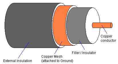
Each technology defines the connectors and cabling types that should be used in order to be able to carry the signals from computer to computer without data loss. Some systems employ coaxial cable which is constructed like this:
-
Signals travel as voltages on the central conductor which is surrounded by a layer of polyurethane filler/insulator that serves to separate the conductor from the ground line and to give the cable shape and stiffness. The copper mesh is wrapped around the filler and is attached to ground at one end; never both as this will form its own circuit called a "ground loop" which will paralyze the bus activity on the central connector. This is protected by an outer coating of insulator usually made of PVC. Coaxial cable takes advantage of the laws of electromagnetic energy field propagation. By measuring the distance between the center wire and applying a field effect formula expressing the relationship between the voltages that the center wire will carry, the mesh can be positioned so that electromagnetic field effect caused by the traveling voltages in the center wire will not extend beyond the copper mesh layer. Conversely no external electromagnetic fields will interfere with the central wire either. This is in theory. A strong enough external field will compromise signal integrity but it would have to be substantial.
-
Coaxial RG-58 cable installations use BNC connectors as the standard connector for attaching the cables to devices. Since the coaxial cable is the basis for a bus physical topology each computer must "tap" into the bus and not interrupt it. This is done with "T" connectors. Two pieces of coaxial cable can be joined using a BNC coupler and the bus must be terminated with 50Ω resistors which also have BNC connectors on them. Here are some examples of these cabling components:
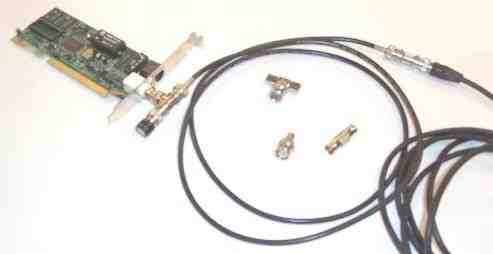
The NIC is attached to a T-connector into which the cable is plugged. The black knob on the other connector of the T is a terminator. The other end of that cable is attached to another cable with a coupler. In the middle of the loop of cable there is a T-connector at the top, another model of terminator below it and a coupler to the terminator's right. Instead of the coupler you could attach a T-connector and plug in another NIC. The physical segment of the bus continues in this way until you reach each end to which a terminator must be attached. The line must stretch unbroken and unbranched from end to end.
-
The two most common forms of coaxial cable used in the PC networking technologies were both Ethernet specifications. RG-8, also known as "thicknet" conforms to the 10Base5 section of the Ethernet specification. This cable is both thick (10mm in diameter) and quite rigid due to the fact that it is physically thick and the central conductor is a solid copper wire, making it fairly difficult to work with when a sharp corner must be negotiated. Signal integrity was however maintained for distances of up to 500 Meters (over 1,500 feet) making it ideal for large network installations that must span large buildings. RG-8 cables feature N connectors, which are screw on connectors with a center tap pin protruding out of the middle and are similar in appearance to cable TV connectors only larger.
-
The other type of coaxial cable used commonly in LANs was RG-58 or "thinnet." This cable is much thinner (5mm in diameter) and is quite flexible not only because is it thinner but also because the central conductor is a bundle of very fine copper filaments called "stranded copper wire." This makes it much more suitable for areas where sharp turns must be negotiated. This cable can maintain integrity according to the 10Base2 section of the Ethernet specification for up to 185 Meters or around 600 feet. Both of these Ethernet technologies use the coaxial cables in a physical bus topology. The picture above is all RG-58 equipment.
-
Thicknet was usually used to span large distances and usually ran through the plenum area between floors of buildings. When it passed over the location of a PC that needed to be attached to the network, a hole would be carefully drilled into the cable sheath and a "vampire tap" would be screwed onto the cable. This clamp-like device had a metal tooth that was inserted into the drilled hole and made contact with the center conductor of the cable effectively branching a connection onto the bus. The vampire tap quite often also includes the actually Ethernet transceiver circuitry as well as the coaxial core tap. In this case the transceiver unit will be attached with a cable with standard male DB15 connectors at the opposite end that connect to the NIC on the PC. The DB15 female connector on the NIC is referred to as an AUI (Attachment Unit Interface) connector and is intended for use with a vampire tap/Ethernet transceiver unit to attach the system to an RG-8 cable. The cable that runs from the vampire tap to the card is referred to as a drop line. According to the Ethernet 10Base5 committee AUI drop lines can be up to 50M in length. The RG-8 cable spanning large distances in the plenums and walls became known as the network backbone. These terms are still used even though the RG-8 cable and the AUI drop cables are no longer used.
-
In RG-58 cable thinnet systems, the cable might run around baseboards or through the partitions of cubicles so that it can reach each workstation directly since the cable is much more flexible. Each station attaches directly to the RG-58 bus cable with a T-connector as illustrated above. RG-58 cables feature a 50Ω impendence meaning that cable must be terminated with a 50Ω resistor to compensate for this and eliminate electronic reflections off of the ends of the cables.
-
Both "Thicknet" and "Thinnet" are certainly deprecated technologies, but 10BaseT while deprecated is still a viable solution and many modern Ethernet technologies are still fully backwards compatible with it and can communicate with these devices. 10BaseT introduced the use of UTP - Unshielded Twisted Pair which has since then completely taken over as the standard cable type for the "copper networks." This cable is rated based on the maximum data communication rate that it supports which in turn relies primarily on the number of twists per foot in the wire pairs within it. Standard Category 3 UTP cable, or simply "Cat3" was used by the original Ethernet specification and features 3 twists of the wire pairs per foot. However, by increasing the number of twists (and other manufacturing characteristics), a cable can carry faster signals (higher frequencies) without the moving electrons causing magnetic fields that distort signals in the other twisted pairs in the cable; an effect called crosstalk. Standard Category 5 UTP features four twists per inch, the necessary modification to allow the cable to carry data at ten times the speed (100Mbps) as Cat 3 (10Mbps). Category 5e is Cat 5 "enhanced" and follows the ISO/IEC 11801 specification for network cabling which refers to it as "Class D" network grade cabling. This has been accepted by the EIA/TIA - Electronics Industry Association / Telecommunications Industry Association 568-B specification for facilities wiring. CAT5e supercedes CAT5 such that CAT5 is no longer made since it does not fully meet the current EIA/TIA specification. CAT6 was recently ratified by ISO and must have even more twists (up to 10 twists per inch) and each wire is also slightly thicker (22 or 23 gauge vs. 24 gauge used in the preceding cable types) and is approved for Gigabit Ethernet (1000Mbps). CAT7 is technically not a form of UTP since it features shielding around each pair as well as a shield around the overall bundle within the external sheath. CAT7 performance specifications have already been published by the ISO, but the network industry has yet to adopt a standard (by the EIA/TIA) which may require a new connector to meet the performance requirements (the old RJ-45 or the shielded variant called a GG-45, may not be sufficient).
-
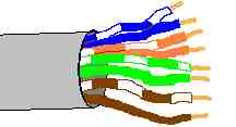
UTP network cable features 4 pairs of wires. Each pair is twisted together through the main external cable sheath, which is usually made out of PVC. The pinouts are as follows:
Pin # Wire Color Function Crossover Connection 1 Orange/White Transmit 3 2 Solid Orange Transmit 6 3 Green/White Receive 1 4 Solid Blue Unused 4, Unchanged 5 Blue/White Unused 5, Unchanged 6 Solid Green Receive 2 7 Brown/White Unused 7, Unchanged 8 Brown Unused 8, Unchanged The orientation of the pins on the RJ-45 connector are determined by pointing the connector towards yourself with the lock tab facing up. Pin 1 is the farthest to the left and pin 8 is the farthest to the right:
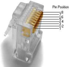
Image from Wikipedia.com
-
The section of the Ethernet specification that discusses UTP is referred to as 10BaseT. A single cable segment may not exceed 100 Meters. UTP cable is a bundle of small individually insulated wires. Each wire is usually 24 gauge AWG and insulated by a thin layer of PVC. To splice UTP requires the removal of the outer sheath of PVC and then the removal of the insulation on each of the eight internal wires. In doing this, conductor pairs often have to be untwisted in Cat5 or higher rated UTP and this effectively destroys its CAT5 rating and it is far more reliable and cost effective to simply purchase complete CAT5 patch cables slightly longer than the measured lengths that are needed rather than fool with it and ruin its high end performance rating. UTP is often reinforced with Kevlar strands running parallel through the sheath with the wire pairs. This cable is used in networks that will feature repeating devices including hubs or switches and is therefore seen in Ethernet Star topologies. Although IBM Token Ring supports UPT Cat5, longer cable runs and numbers of stations on a ring are possible when using STP or Shielded Twisted Pair which wraps the four pairs in metal foil and then wraps that with the outer sheath. STP can be used in Ethernet networks since it is far more reliable, but it is quite expensive and so is rarely seen in large networks where the cabling infrastructure is already expensive enough.
-
The transmissions that we are referring to are the rising and falling of voltages on a single long cable that represent binary one's (voltage), and zero's (no voltage). Signaling of this kind is referred to as baseband communication. The cable carries only one signal channel upon which data can travel directly related to the voltage levels in the cable. There is another type of communication through a cable called broadband. In broadband more than one data stream can flow through the cable at the same time. This is because the data rides within a radio frequency sine wave or carrier wave. The transmitter and receiver are tuned so that they will only read the data out of the current flow waves of a specific frequency and will ignore all of the others occurring in the wire simultaneously. If you have ever changed the channel of a cable TV you have watched the broadband communication technique in action. All of the cable TV networks television channels are traveling through a single wire using broadband technology. Ethernet is a set of baseband technologies.
-
The specific encoding used by the hardware circuitry of an Ethernet NIC to transmit the information between each other on the cable is referred to as Manchester Encoding. In this encoding technique timing or synchronization is established by the digital data itself and the individual binary information bits are encoded by the changes in the voltage, not the level of the voltage. Where typically we think of a wire carrying binary data does this by saying that if it has no voltage that is a "0", and if it has voltage that is a "1" Manchester encoding says "If the voltages drops sharply within the time slice of the bit, that is a "0", if the voltage rises sharply in the time slice of the bit, that is a "1."
-
The specific document that defined Ethernet at the Logical Link Control layer was the IEEE 802.2. This however, functions only as a part of the Ethernet specification. The physical layer (cabling, signaling, etc) and the MAC - Media Access Control, layer which is Ethernet itself, is fully laid out in the IEEE 802.3 document. This describes the technology at the engineering level defining impedance and signal attenuation in the cables, as well as all aspects of the technology including the MAC layer "rules of contention" for handling traffic called CSMA/CD – Carrier Sense/Multiple Access with Collision Detection. These CSMA/CD MAC layer rules are Ethernet much more so than the physical technologies that carry it between stations.
-
The IEEE 802.3 document also describes 10Base5, 10Base2, and 10BaseT. The prefix 10 means that the technology will communicate at 10Mbps. The word Base indicates that it is a Baseband technology. The 5 indicates that 10Base5 has a maximum single cable length of 500 Meters (thicknet). The 2 means that 10Base2 supports a maximum cable length of 185 Meters or roughly 200M (thinnet), and the T means that 10BaseT will use unshielded twisted pair cables (with a maximum single cable length of 100M not evident in the committee name.)
-
In Ethernet of any type, the main issue in the design and implementation of the network is the concept of the collision domain. Since signaling collisions do occur, it is important to understand how they occur and how the system deals with them. Our discussion will begin with a 10Base5 collision domain.
-
This network is a bus in which all PC's NIC's are physically connected to the same stretch of RG-8 cable. Since each PC is an independent system it may choose to transmit a packet at any moment, if two systems initiate transmission at the same time a signal collision will occur that will garble both transmissions. Ethernet cards therefore are designed at the circuitry level to do the following:

CS - Carrier Sense: The NIC will listen to the cable first. If the cable is "quiet" then it will immediately begin to transmit. If it is busy, then it will continue to monitor the cable until it becomes available, then begin to transmit. MA - Multiple Access: All Ethernet NIC's are free to begin transmitting whenever they need to and all Ethernet NIC's have equal access to the network and all Ethernet NIC's have access to the entire network (collision domain). CD - Collision Detection: NIC's can only actually detect a collision when it occurs to the packet that they are in the process of transmitting, passive cards waiting for the media to become available 1) are not designed to detect the collision, 2) could do nothing about it if they did (they cannot transmit a signal to the other cards because two cards are already jamming each other on the cable as it is). This behavior is called LWT - Listen While Talking. Collision response step #1 - Stop transmitting and initiate jamming signal: Once a collision is detected this means that at least two NIC's are transmitting simultaneously. The NIC will immediately cease transmission and transmit a jamming signal; this is intended to make sure that the minimum packet length will be met so that the other NIC will detect the collision as well. Collision response step #2 - Random backoff algorithm: The NIC will now enter a "backoff" mode. It will wait a short random period of time, calculated using the binary exponential backoff algorithm, and then attempt to transmit again. The assumption is that since the wait to retry time period is randomly counted that one NIC will attempt a retry before the other, the other will detect the activity in the line and suspend transmission due to the carrier sense feature above. Collision response step #3 - Multiple collision random backoff algorithm:In the event that the card is involved in another collision upon retry (it may not be with the same card as the first collision!), it will send the jam signal, and wait another random backoff period. Each of these backoffs is calculated using a doubling variable. The different Ethernets specify 10 to 16 retries before reporting the packet undeliverable to the upper layers. -
One of the main features that control the maximum physical size of the entire network is the signal propagation delay across the span of the network. Restated, how long does it take a signal to travel from one NIC at one end of the RG-8 cable to a NIC at the opposite end of the cable? This time delay will affect the ability of the two NIC's to detect collisions and take the appropriate actions.
-
If the smallest possible Ethernet packet were a single bit in size, then the entire transmission would last for 1/10,000,000th of a second (10,000,000 bits per second). The speed of electrons through copper wire is approximately 2/3 the speed of light through vacuum or 200,000Km/sec. Multiplying these two values together (after converting to the same units of distance: 200,000,000M/sec X 1/10,000,000th sec = 20M. This means that NIC's farther than 20M apart would never know that a collision had occurred. Therefore Ethernet specifies a minimum transmission size of 64 bytes of data or 512 bits. packets smaller than this are illegal and called "runts." The largest possible packet is 1518 bytes or 12,144 bits. If a single transmission on the medium exceeds this, this is also illegal and the transmitter is said to be "jabbering." Each single transmission block of data is called a frame and contains specifically located fields that carry specific information about it. These Ethernet frames are constructed by the LLC sublayer of the Data Link layer programs running on the system.
-
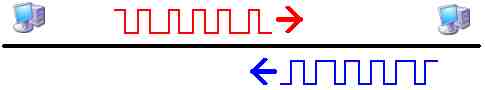
The network must be constructed so that the farthest transceivers cannot possibly transmit an entire frame to completion and then stop transmitting before a collision. To illustrate:
-
In this network the PC's are too far apart. The one on the left has completed the transmission of an entire red frame and is no longer capable of even detecting the collision that is about to occur. Remember that Ethernet transceivers are designed aorund the LWT capability; they can only detect collisions while they are transmitting. The transmitting PC is about to finish its blue transmission and will not be listening by the time the garbled red packet arrives and will not be able to tell that a collision occurred either. Neither system will know what happened or why the packets that they each receive are full of errors.
-
Therefore the farthest points on the network cannot exceed, half the size of a frame. So that half way through the frame transmission, the leading edge of the waves will be at the midpoint of the wire where a collision would occur and be able to reach the transmitting device while it is still transmitting the current and now damaged frame. Multiplying half of the 512 bit minimum sized packet by the length of a bit (20M) yields a maximum theoretical distance of 5120M. However, there is much more to the story than can be dealt with here. There is the problem of the resistance of the cable which causes a phenomenon known as "voltage drop" and "signal attenuation." Some cables are better than others at dealing with this problem. Another problem is distortion or noise. Each bit is in actuality trillions of electrons crashing through the outer electronic shells of trillions of metal atoms in the wire. The farther the distance that this group of electrons has to travel the more of them will take longer routes through the metal and fall out of phase with the pulse, some will shoot through easy pathways, others will meander about through long twisted pathways and others will get completely lost along the way (resistance). The is all unavoidable but it can be controlled to a limited extent by the quality of the copper cable. Its tendency to "blur" the cloud of electrons traveling through it that represent the data is the main cause of signal attenuation. Noise is another problem mostly caused by outside sources of electromagnetic waves and fields that introduce their own electron flow within the wires and also distort the real transmissions. Distortion caused by electromagnetic fields is called EMI - Electromagnetic Interference, and distortions caused by radio waves is called RFI - Radio Frequency Interference. Both are significant problems when using UTP cable.
-
Each type of cable has a specific capacity for carrying the signal in tact over a maximum distance before it becomes too garbled to be considered reliable. For RG-8 this is 500M. For RG-58 this is 185M and for UTP this is 100M.
-
At the physical layer there are devices that can receive the attenuated and distorted signal and therefore effectively rectify the signal by rebroadcasting it down another stretch of cable. The most common of these in earlier Ethernet networks was called a repeater. This is a pure physical layer device that simply rectifies the signals reaching it and rebroadcasts them down the opposite cable with no regard to the information within the signals. When connected to RB-8 cables they can in theory carry the collision domain to a size where the minimum packet could fit onto the cables and the collision domain would be incapable of functioning. The IEEE 802.3 specification for 10Base5 Ethernet networks indicates that the collision domain can never exceed a maximum physical segment length of 2500M or roughly half the maximum theoretical distance calculated above.
-
Once a collision has been detected the detecting system must transmit the jamming signal, which is 48 bits long, then cease transmission. The recovery time between transmissions is a window into which 96 bits would fit: no transmitter should initiate transmissions during this period after a frame has ended. This recovery time window shrinks when physical devices are placed onto the cable that introduce delays in the propagation of the transmission, which repeater circuits do. It is this shrinking recovery time window more than anything else that dictates the well known 5-4-3 Rule.
-
The Ethernet 5-4-3 Rule for 10Base5 networks states that the largest collision domain possible can be constructed using 5 physical segments of cable (500M each) connected by 4 repeaters, but populated segments must be separated by unpopulated segments to cut down on intersegment collisions.
-
The minimum separation between the physical connections of the systems to the RG-8 backbone is 2.5M. RB-8 cable was usually made a bright and distinctive yellow color marked with black bands every 2.5 meters indicating exactly where a tap could be made into it without tapping into it within the minimum 2.5M separation distance requirement for transceivers. This is to prevent the signals from being so close that a simultaneous broadcast by both transmitters would be in wave phase with each other and be very difficult to detect. Since a wavelength is roughly 20M then the rule implies that if transceivers are close to 1/10th of a wavelength apart then their waves will be in phase and inseparable from each other.
-
The maximum number of transceivers allowed on the entire Ethernet collision domain is 1024. However, if the minimum separation between station attachments is strictly obeyed it can be seen that on any of the 3 populated segments (the 3 in the 5-4-3 rule, the 4 means maximum of 4 repeater devices and the 5 of course means a maximum of 5 physical cable segments) 500 ÷ 2.5 = 200. Therefore the theoretical maximum number of stations that can be attached to this network would be 200 stations on each of the three populated segments. In practice the specification allows a maximum of 100 nodes per segment of a 10Base5 network allowing for a maximum of 300 nodes in the network.
-
The efficiency of the network dramatically declines as the number of stations increases. Increasing the average distance between the stations also negatively affects the performance of the collision domain as well.
-
10Base2 also allows the 5-4-3 Rule but each cable segment is limited to 185M. Multiply this by 5 = 925M total length of the collision domain. Here the issue is not the time delay of propagation of signals but the signal attenuation and noise. Again a minimum 2.5M separation limit between T-connectors would be expected and each segment can have a maximum of 30 nodes allowing for a total of 90 on the entire collision domain. This limit is again related to the quality of the cable and not the capacity of the Ethernet CSMA/CD rules.
-
10BaseT networks function fundamentally differently from the other two. Instead of RG-8 or RG-58 coaxial cable, Unshielded Twisted Pair category 3 or better cable is used instead. Since the conductors are far thinner and the noise is handled by twisting the conductors rather than shielding them within the grounded conductor, 10Mhz signals undergo too much loss beyond 100M to be acceptable for the specification. Also the nodes are not attached to this cable in bus fashion but rather each cable attaches to a central interconnectivity device at one end and to a single NIC at the other end. The interconnectivity device is responsible for providing the cicuitry to propagate the signal to other nodes. In the early days this device was referred to as a concentrator, but the term hub has become far more common. The stretch of cable that runs from the hub to the NIC is by definition a single segment of the network and it can only be populated by a single node unlike the population situation of the bus cables just discussed above. The hub and the NIC each always provide permanent automatic termination of the eight wires within the cable which by the way require 100Ω termination.
-
A hub through circuitry emulates the bus by broadcasting a signal that it is receiving on one port out all of the other ports. It can be thought of therefore as a multiport repeater. The hub's circuitry introduces a signal propagation delay which will affect the maximum functional size of the collision domain. 10BaseT can use the 5-4-3 rule in which 4 hubs are used instead of repeaters but the populated part of the rule does not apply:
-
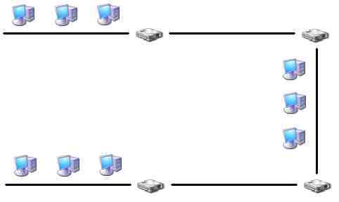
The main rule to remember in 10BaseT collision domains is that if a signal has two different pathways that it can take through the hubs it will take both paths and cause problems. This must be avoided.
-
Looking at the PC on the bottom left of the illustration above, the first segment is the 100M wire that runs up to the first hub to which it is connected. This hub is connected by another 100M segment of UTP cable to the upper left hub. This is the second of the five segments. That hub is attached by a 100M cable to the upper right hub: third segment and third device. This is attached by the fourth 100M segment to the lower right hub, the fourth device. This is attached by the fifth 100M segment to the PC at the lower right corner of the picture. The signal can only travel along this one pathway between the two systems and it travels across five segments of cable through 4 devices. The reason the population rule does not apply is because there can be only a single system attached to each 100M segment. The PC at one end and the hub at the other.
-
The 10BaseT network could in practice have 1024 units if the hubs had enough ports to accommodate them, but the collision domain would most likely get seriously bogged down to the point that many frames end up being reported as undeliverable because the transceiver tried repeatedly to transmit it and kept colliding with other transmissions. In this case, this LAN has failed. The best bet would be to break it up into two or more smaller Ethernet collision domains and interconnect them with some other technology such as routers.
-
One last note about Ethernet: in applying the 5-4-3 Rule, segment types can be mixed if the repeaters or adaptors are built for it. Such devices are said to be or contain "media converters." That is, a system can attach to a hub using UTP cable. The hub can have a BNC connector and attach to a 185M stretch of RG-58 (which must remain unpopulated and obey the –3 part of the rule) which attaches to a repeater with an N connector for an RG-8 500M run of cable that is populated and ends in another such repeater which attaches to another unpopulated run of 185M of RG-58 which connects to a hub which has a PC attached by a 100M UTP cable.
-
IEEE 802.2 defined the structure of an Ethernet Frame and therefore is strictly considered the Ethernet LLC (Logical Link Control) sublayer specification. 802.2 was superceded by the IEEE 802.3 specification which describes the Ethernet MAC (Media Access Control) sublayer and the CSMA/CD behavior which defines Ethernet as a unique networking technology and has separate subcommittees for describing the physical specifications for 10Base5, 10Base2, 10BaseT, several 10Base fiber optic technologies as well as the 100Base technologies and the new Gigether and 10G Ethernet which is currently under development.
-
The 100Base technologies use a frequency of 100Mhz and must have a collision domain 1/10th the size of a 10BaseX collision domain. It should also be noted that none of the original cabling used in the 10Base technologies will carry 100Mhz signals without dramatic noise and attenuation loss over very short distances. The minimum cable that can be tried with 100BaseTX is Category 5 UTP although the network is out of specification in this case since Cat5e or better is specified in the IEEE, ISO and EIA/TIA specifications.
-
100BaseTX does not obey the 5-4-3 Rule at all. The maximum size of the collision domain is 205M from node attachment to node attachment. Furthermore, a maximum of two Class II (high speed) repeaters is permitted between the nodes. If two repeaters are used, the maximum distance between the two is 5M. This is to allow for Cat5e patch panel connectivity.
-
Server technologies are generally speaking 100% standard PC compatible technologies. The only feature that actually makes them "server" technologies is their price tag. In other words anyone can build a PC-based server and/or add server components to any PC. Selecting a PC-based server network interface card depends ultimately however on the desired DTR between the server and the rest of the network. This DTR is ultimately affected by the motherboard more so than the type of network technology chosen for the NIC. Standard PC's are generally equipped with the standard PCI expansion bus slots which are 33MHz and have a 32-bit wide data bus. This yields a DTR of 133MB/sec. 1000BaseX Ethernet networking technologies are 1000Mbps or 125MB/sec. This means that either the NIC can be in operation or the hard drive (ATA-133, which is 133MB/sec) but not both at the same time. PCI-X in its current form runs at 133MHz with a 64-bit wide data bus which yields a DTR of 1066MB/sec which would allow the server to stream data continuously from the hard drive out to the 1000BaseX NIC. PCI-Express gives each slot its own serial 250MB/sec connection to the controller and can "bundle" multiple lanes so that an x2 slot can allow the expansion card a total DTR of 500MB/sec, an x4 card can have a DTR of 1000MB/sec and so on. The PCI-Express bus is slowly becoming more commonplace in the end-user PC, but PCI-X is strictly a "server" technology only found on expensive, high-end motherboards. Nevertheless it does exist and end-users could obtain such a motherboard and PCI-X expansion cards for it.
-
With 1000BaseT, the copper networking technologies are certainly capable of server-level performance, however the copper cable technologies are still fairly limited in range (100M or so) and still susceptible to EMI/RFI as well as being easily tampered with including being tapped. For greater distances, improved data integrity and security the fiber optic based technologies are necessary.
-
In the early days of Ethernet a fiber optic version exosted called FOIRL - Fiber Optic Inter-Repeater Link This hardware and Data Link layer equipment would ultimately become the inspiration for the formal fiber optic technologies Ethernet specification known as 10BASEFL, 10Mbps transmissions over duplex fiber optic cables, one for transmit commonly labeled "Tx" and the other for receive "Rx".
-
Fiber Optic cabling is impervious to EMI and RFI because it is not carrying electron pulses and does not contain electrical conductors of any kind. The optical conductive core is instead optical grade glass surrounded by another layer called the cladding. This is then surrounded by protective layer called a "buffer" which in turn is surrounded by the exterior proptective layer called the "jacket" There are two major categories of fiber optic core/clad cables: single-mode and multi-mode.
-
Multi-mode optic fiber cable cores range from 50µ to 62.5µ and are embedded within a 125µ cladding. Light waves generated by either a pulsating laser or LED do not travel in a straight line through the center of the core but instead bounce off of the core/clad boundaries down the length of the cable:
In multi-mode fiber, light waves from the light source on the left reflect off of
the core-cladding boundaries all through the length of the cable and arrive out of
synchronization at the far end, hence MMF cables have a shorter effective range. -
Single-mode optic fiber cores are usually 8µ surrounded by the 125µ clad layer. Light waves do travel through the center of the core and refract around curves in the cable and never bounce off of the core/clad boundaries. Pulses of light within the single-mode fiber remain very tightly confined and do not lose much intensity from the reflections typical of multi-mode optic fiber cable. As such single-mode optic fiber cable can carry signals much farther than multi-mode can.
In single-mode optic fiber, only the light waves that travel parallel or very close
to the parallel to the center of the much narrower core can reach the opposite end,
those waves that do hit the core/cladding boundary are not reflected as many times as
they are in multi-mode fiber and arrive in synchronization with the actual signal. -
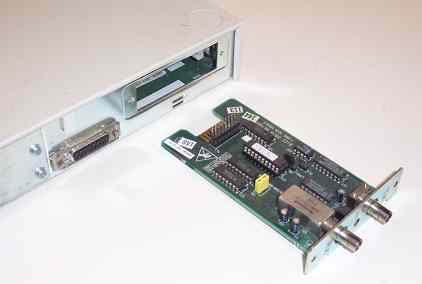
FastEthernet, defined as 100Base-TX, also has a fiber optic variant known as 100Base-FX. Transceivers are also categorized by their cabling type in which they require either single-mode or multi-mode. To further complicate matters, 100Base-FX also features LOMMF - Laser Optimized Multi-Mode Fiber which has greater range than normal MMF - Multi-Mode Fiber cable. Devices requiring LOMMF may not function at all with "regular" MMF cable. 100Base-FX has a half-duplex variant capable of a maximum cable length of 400M while the full-duplex variant has a maximum cable length of 2KM using MMF. 100Base-FX single-mode transceivers in full-duplex mode can span far greater distances. 100Base-SX uses multi-mode fiber up to 300M and the same wavelengths as 10Base-FL making it backwards compatible to that technology while true 100Base-FX is not. 100Base-BX uses multiplexed transmit and receive over a single strand of single-mode fiber and is not compatible with any other technology. Below is a typical 100Base-FX Multi-Mode Fiber internal PCI NIC. The multi-mode fiber cable has the matching SC - Standard Connector connectors that snap straight into place.
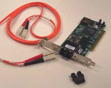
Allied Telesys 100Base-FX internal PCI NIC with dual SC connectors.
As with most fiber optic network technologies, one connector is labeled
"Rx" for receive, the other "Tx" for transmit. -
A more economical and practical solution is to install a media converter. The one below can convert either 10BaseT or 100BaseTX copper Ethernet I/O to 100BaseFX I/O. The cable ends have the same ST - Straight Tip connectors as the media converter.
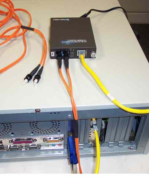
Trendnet 100Base-FX/100BaseTX External Media converter. For less than
$100 per unit can convert to secure fiber optic communication lines
to span insecure areas of the facility. -
Gigabit Ethernet has several variants that were independently developed and wrapped into the official specifications as the IEEE 802.3z subcommittee specifications:
- 1000Base-SX: 850nm NIR - Near Infrared laser light source. Maximum cable length of 220M using 62.5µ/125µ MMF cable, 500M using 50µ/125µ LOMMF cable.
- 1000Base-LX: 1300 - 1310nm IR - Infrared laser light source. 1000Base-LX is optimized for use with SMF cable. Maximum cable length of 5KM using 9µ/125µ SMF cable. Can use MMF up to 300M, and up to 550M with a special diffusion cable adapter.
-
Gigabit Ethernet also includes formal definitions of a modified version of 1000Base-LX called 1000Base-LH (Long Haul) as well as at least one Cisco proprietary technology:
- 1000Base-LH: Modified 1000Base-LX using 1310nm IR laser and 8µ/125µ SMF cable to achieve a maximum single cable length of up to 10KM.
- 1000Base-ZX: Cisco proprietary technology using 1550nm IR laser and 8µ/125µ SMF to allow maximum cable lengths of up to 70KM and up to 100KM using "Dispersion Shifted" SMF cable.
-
EFM - Ethernet over the First Mile is formally defined in the IEEE 802.3ah specification as EFMF - Ethernet over the First Mile over point-to-point Fiber which includes technologies that allow Ethernet frames to "stay native" over large distances (Metropolitan Area Networking) without having to be stripped and converted and retransmitted over other technologies i.e. EoPPP - Ethernet over Point-to-Point Protocol or Ethernet over ATM. This specification includes 100BaseX and 1000BaseX technologies of which many are fiber optic based:
- 100Base-BX10: Multiplexed transmit/receive on a single strand of SMF optic cable. Transmit at 1260-1360nm and receive at 1480-1580nm up to 10KM. 100Base-BX10-D transceiver can only communicate with a 100Base-BX10-U transceiver (which uses the opposite wavelengths for transmit and receive)
- 100Base-LX10: Dual (separate Tx/Rx lines) SMF optic cable at Tx/Rx lasers at 1260-1360nm wavelength. Maximum cable length up to 10KM.
- 1000Base-BX10: Multiplexed transmit and receive on a single SMF cable at Tx = 1260-1360nm, and Rx = 1480-1500nm. Maximum single cable length of up to 10KM. 1000Base-BX10-D transceiver can only communicate with a 1000Base-BX10-U transceiver (which uses the opposite wavelengths for transmit and receive)
- 1000Base-LX10: Dual (separate Tx/Rx lines) SMF optic cable at Tx/Rx lasers at 1260-1360nm wavelength. Maximum cable length up to 10KM.
-
Gigabit Ethernet has two copper variants: 1000Base-CX an early working version with maximum cable length of 25M over special shielded cables included in the original 802.3z specifications. The technology's goal was to provide high throughput connections between servers and server framework connectivity ports on large switches. It is now considered obsolete in favor of 1000Base-TX, defined in the 802.3ab specification, which allows 1Gbps communication over standard CAT5e (preferably CAT6) UTP copper cabling. 1000BaseT achieves this speed by using three pairs simultaneously at 333MHz each which is the maximum possible DTR for this category of cable. 1000BaseT is a perfectly viable server network connectivity solution for affordable high throughput peripherals and server framework technologies, but is as insecure as any copper technology. As such, the server-to-framework cabling should not extend beyond the physically secured facilities, i.e. the telecommunications/networking closet.
-
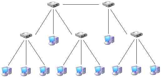
One of the first fiber optic based networking technologies intended to provide large maximum cable distances and highly secure cable transmissions outside of the secured facilities was FDDI - Fiber Distributed Data Interface. FDDI was not intended to attach individual nodes, instead the intent was to provide a high throughput, high reliability, long distance, and secure connection between network interconnectivity nodes, i.e. network framework connection points. In other words FDDI is a MAN - Metropolitan Area Network solution providing a fiber optic backbone that can interconnect multiple conventional copper based LAN's between buildings where existing copper based solutions are inadequate. FDDI was developed during the era of 10Base-T Ethernet and so did provide a very high speed backbone. By today's standards it still has its uses in that it can span a total distance of 100KM (62 miles), as a fiber optic technology it is extremely reliable over these distances, and very difficult to tap into. FDDI is also very robust in that it uses a dual physical ring topology such that if the primary ring is damaged, it can "heal" by automatically sensing the situation and starts using the secondary ring instead. If both are damaged it can wrap the ring using segments of both rings to continue functioning.
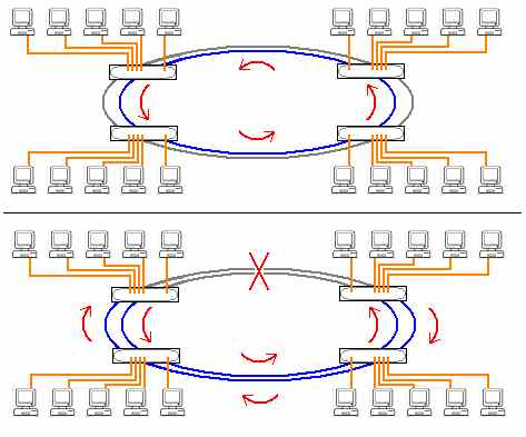
In the top, each copper LAN is attached to the switch that also has FDDI links
the inner ring is working and the outer ring is dormant. In the bottom, the rings
have been broken, the upper left and right FDDI nodes wrap the ring back into the
outer one which is activated. The FDDI ring is thereby completed and continues to work. -
FDDI is a complete networking technology with specifications at the physical and data link layers. At the physical layer it is a dual ring topology each device attaches a cable from itself at the "RO" or "Ring Out" connection to the next device's "RI" or Ring In" connection until the last cable brings the Ring Out connection back to the first device's Ring In connection. At the data link layer it is defined as a ring topology as well in which the devices pass a small "token" frame around the ring. If a device receives the token and wishes to transmit, it makes its transmission and attaches the token to the end of the transmission frame. The next downstream neighbor may append its transmission to the first one and attach the token to the end of this frame. FDDI supports frames of up to 4500 bytes to facilitate this communication method.
-
Because FDDI has its own frame types and Media Access Control behaviors, it is not compatible with fiber optic forms of Ethernet and it uses different connectors in general to prevent attempting to connect the two different types of network device together.
-
Modern switches allow for the optional attachment of a fiber optic interface converter. This is not a complete NIC, just the transceiver, the rest of the NIC circuitry is permanently embedded in the circuitry within the switch. The cable ends have the matching ST - Straight Tip connectors as the media converter. The 10Base-FL fiber optic interface converter below is intended as a long distance secure connection to the switch. Switches also offer the optional attachment of a GBIC - Gigabit Interface Converter. These are very similar in appearance to the 10Base-FL interface converter shown below, and again are not complete NIC's but rather just the fiber optic transceivers for the 1000Base NIC that is embedded into the backbone circuitry called the fabric of the switch and allow the node that attaches through the GBIC to maintain Gigabit Ethernet communications with up to 10 different 100Base ports simultaneously. This would indeed be an example of a server physical framework solution.
Rear of a typical 3COM 100BaseTX 24-port rackmount switch. The expansion plate
has been removed so that the 10Base-FL fiber optic interface converter can be
installed. These are proprietary expansion modules only available from the OEM. -
Fiber optic cabling connectors are seen in many different forms in the networking industry including the two already shown above: ST - Straight Tip which has a BNC style connector that twists about half a turn to secure the connector and the SC - Standard Connector which is square and snaps into place and has a small plastic "catch" that is squeezed in to allow it to release again.
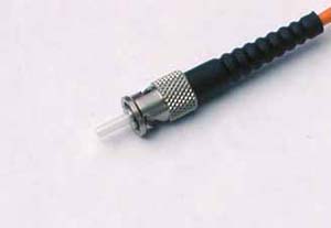
Optical fiber male ST-type connector, end of cable.
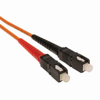
Optical fiber male SC-type connector, end of cable.
-
FDDI uses its own type of duplex connector referred to simply enough as an FDDI connector.
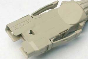
Duplex optical fiber male FDDI-type connector, end of cable.
-
The FDDI connector and the ST and SC connectors which have been used in 10BASE-FL and 100BASE-FX, are commonly found but they are aging. Modern optical fiber cables and devices are using other types of connectors more and more including: MT-RJ - Mechanical Transfer - Registered Jack, FOCIS6 - Fiber Optic Cable Intermateability Standard Type 6 (a.k.a. "fiber-jack") and LC - Lampert Connector.
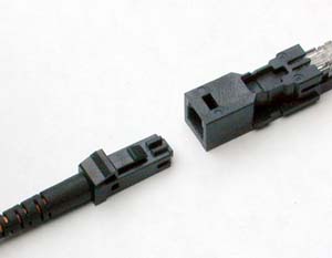
Optical fiber male (left) and female (right)
MT-RJ-type connector, ends of cable.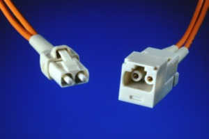
Optical fiber duplex male (left) and female (right)
"fiber-jack"-type connector, ends of cable.
Optical fiber duplex female LC-type connector, Cisco Transceiver Interface Module
(installs into one of their rackmount network connectivity devices)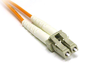
Optical fiber duplex male LC-type connector, end of cable
-
The advantages of using any fiber optic technology can then be summarized as:
Security: Fiber optic lines are extremely difficult to tamper with and hence difficult to tap.
Distance: Fiber optic communications experiences very little loss data loss over long distances allowing less expensive MMF technologies to have maximum single cable lengths from 220M to 550M while SMF based technologies average from 2KM to over 70KM.
Data Integrity: Fiber optic communications experiences almost no interference or loss of data integrity on cables at or below the maximum length of the specification. And because the cables are not electrical conductors do not generate EMI/RFI and are not affected by these either making fiber optic networking technologies suitable and sometimes the only solution for areas where these are prevalent.
-
Fiber optic disadvantages are then:
Expensive: Fiber optic devices and cables are far more expensive than their copper based counterparts. A typical 1000Base-TX NIC can be found for as little as $20, while the cheapest gigabit fiber optic NIC is still close to $100. A 100M Cat5e cable can be found for $60, a 100M fiber optic cable is generally more than $200.
Compatibility issues: Few fiber optic devices are compatible with other technologies. Even two different devices claiming to be the same technology may not be compatible with each other or with the cable type. I.e. one 100Base-FX device may not work on anything other than 50µ core MMF cable, while the other will not work on anything other than 62.5µ core MMF cable. The two devices cannot therefore be attached to each other.
Difficult/Costly to support: Knowledgeable technicians with experience in fiber optic systems will be few and far between and they will not be inexpensive. Cutting and splicing fiber optic cable is definitely a difficult and expensive skill to acquire and master. Designing and implementing fiber optic based systems is troublesome at best, making sure, for example, that the transceiver interface module on the switch will in fact communicate properly with the NIC intended for the server. Transceiver and cable connectors as well as the cables themselves are extremely fragile and easily mishandled and broken. The tool to test for a broken fiber optic cable costs thousands of dollars.
Review Questions
-
Ethernet itself is defined by its behavior in what layer? What is this behavior called?
-
Ethernet began with three copper media based committees. Name them.
-
What two Ethernet types (committees) use physical bus wiring? Name the cable types used in each.
-
What is the maximum single segment length allowed in 10Base2 Ethernet networks?
-
What is the maximum single segment length allowed in 10Base5 Ethernet networks?
-
What is the maximum single segment length allowed in 10BaseT Ethernet networks?
-
What type of cable is used in 10BaseT committee Ethernet networks? What is the minimum category of this cable that can be used?
-
What is the minimum separation between vampire taps on an RG-8 backbone? What is the maximum drop line length?
-
What is the theoretical maximum number of nodes on an Ethernet network?
-
Aside from excessive traffic conditions, what else restricts the maximum number of nodes that can actually be connected to an Ethernet network?
-
What is the absolute maximum number of nodes that can be connected onto a 10Base2 Ethernet network? What is the absolute maximum number of nodes that can be connected onto a 10Base5 Ethernet network?
-
In implementing a large Ethernet network you realize that you will be forced to use the 5-4-3 rule. What does each number in the rule mean?
-
In order to be able to connect the largest number of nodes spanning the greatest distance in your 5-4-3 rule Ethernet network, what committee type should be used in the unpopulated segments? What committee type should be used in the populated segments?
-
When choosing a Network Interface Card for a PC, list the factors involved:
-
While NIC's a physical networking devices, what OSI Model Layer device are they?
-
What part of the 5-4-3 rule does not actually apply to a pure 10BaseT network and why?
-
Describe the functions built into the NIC (and/or its driver) that make it work as an Ethernet transceiver:
-
Indicate the Pin to Pin connections for an Ethernet crossover cable:
-
While 802.2 does describe the structure of an Ethernet Frame, what IEEE specification truly fully describes Ethernet?
-
What was the original Ethernet over fiber called? It was formally defined in the original Ethernet specification as what subcomittee name?
-
What is FastEthernet over fiber called?
-
What are the two main types of fiber optic cables used in computer networking? What are their typical core/cladding diameters?
-
List and describe the advantages of using fiber optic networking technologies.
-
List and describe the disadvantages of using fiber optic networking technologies.
-
Describe and contrast Multi-mode and Single-mode fiber optic cables.
-
What are the two main types of light sources used in fiber optic networking? Which one would seem to be capable of greater distances given the same cabling?
-
List and describe all 100Mbps Ethernet technologies and give their IEEE subcommittee designations and numbers?
-
What other fiber optic based networking technology has the same throughput as 100Base-FX? What physical topology does it use? What logical topology does it use?
-
FDDI is normally used to interconnect LAN's to form a what? What is the maximmum cabling distance around the FDDI ring? What is the largest frame size?
-
10Base-FL would likely use what two connector types?
-
Fiber Optic Gigabit Ethernet would likely use what connector types listed above?
-
List and describe all Gigabit Ethernet technologies covered in the IEEE 802.3 specification and give their official IEEE designations and numbers.
-
What fiber optic 100Mbps technology is theoretically backwards compatible with FOIRL transceivers?
-
An economic solution to interconnect two nodes 9KM apart at 100Mbps would be?
-
Most fiber optic nodes use separate transmit and receive lasers and cables, what technologies above feature a single cable connection? How is the uplink/downlink information separated?
Copyright©2000-2008 Brian Robinson ALL RIGHTS RESERVED