CET2176C Server+ Service and Maintenance Lecture #12 - RAID's
Materials: A Complete Working PCTwo additional HDD'sOne blank floppy disketteStudent CD-ROM: "Room6359"Student Diskette: "New Boot A Ver. 2+" A Complete Working PCTwo additional HDD'sOne blank floppy disketteStudent CD-ROM: "Room6359"Student Diskette: "New Boot A Ver. 2+"Objectives: The features and functions Windows 2000 Advanced Server Disk Manager,Basic Disks and Dynamic Disks,The reasons for implementing the RAID choices,The minimum system requirements for implementing each RAID,The preparation and installation of the drives,The implementation of the RAID,The testing of the RAID.Competency: In this module the student will become familiar with the concepts of RAIDs including how to prepare and choose physical hard drives for use in a RAID, the differences between hardware and software level RAIDs, the planning of RAID volumes and the implementation of these volumes on the system. The student will simulate various system drive failures and learn how to access the compromised data and return the system to full functionality. |
Preparation
-
Windows 2000 Server's Disk Management will now be used to create software level RAIDs. Remove the case from the PC and be sure that the drives are properly jumpered. Attach the two additional hard drives to the secondary ATA controller with the additional cable provided. Install the internal rack mounted drive into the rack bay and turn the key to the "On" position. Leave the two additional drives resting on top of each other on top of the drive bay area of the case frame.
-
RAID - Redundant Array of Inexpensive Disks
The definition is also listed erroneously as Redundant Array of Independent Disks but this appears to be various authors attempting to redefine the original meaning. True, SCSI hard drives are not inexpensive, but a RAID allows a group of small drives to appear like one huge drive which would be expensive. So if one were to purchase a single 300GB drive these days (March, 2004) it would cost about $1500. But a 36GB SCSI drive can be found for as little as $125. Setting up a RAID of 8 of these to appear as a single 288GB drive will cost $1000. Therefore the savings paid for the controller (which is more powerful than a comparable ATA controller) cables and terminators and still has change left over. So the name was never intended to mean that the SCSI drives are inexpensive because they are not, it reflects that a RAID can create a virtual drive that would physically be far more expensive if not so big that that have not even been made available to the market yet. There are already RAIDs that appear as drives larger than a TB which are not even generally available yet.
-
RAID technologies are strategies for logically relating the physical disks to each other. This relationship can be done either through hardware in which the controller card and its onboard BIOS are configured to relate the drives to each other, or through software at the operating system/device driver level. Hardware level RAID controllers make the RAID appear to the operating system as a single, simple "INT13h" device. This means that at the very lowest level of access the operating system and utilities will always be fooled into "seeing" the RAID disk group as if it were one big single hard drive. Hardware RAID cards are highly reliable because their program code that controls the access to the RAID and translates read/writes from single simple disk into accesses across the RAID disk group is stored on a ROM BIOS chip and it therefore cannot be corrupted. And this code is executed by the onboard controller circuitry and not the CPU of the PC. Even if the OS crashes the CPU and the regular RAM address space of the system this will not affect the controller so the last disk access will be handled properly. Windows may corrupt its own files on the disk but the controller will not corrupt the RAID storage of the data.
-
Software level RAIDs are far less reliable because the program code controlling the translation of disk read/writes out to the RAID disk group does reside in regular RAM and is running under the operating system. As such it can get corrupted and it will crash when the system does. Therefore this can corrupt the RAID storage distribution of a file across the group.
-
However, a software level RAID is still far better than no RAID at all and it is highly recommended on budget Windows 2000 Servers since the feature is already built into the OS which is already paid for anyway: in other words its free, so why not? And with the dramatically reduced prices of ATA drives as they are begin phased out, even a mirror of the 40GB drive holding the C: partition would cost less than $100 and be worth its weight in gold, the day that original C: drive fails.
-
One of the disadvantages of hardware RAID cards aside from their high price, is that often they cannot RAID drives of different types or even capacities. Newer controllers seem to be more powerful and can handle a mismatch of physical drives but this should be investigated prior to purchasing a $1000+ SCSI RAID controller. Software level RAIDs can usually configure any group of hard drives into RAIDs because the operating system has the drivers for accessing each drive and it does recognize them individually and it is the software that is managing the RAID.
-
Here are the major basic categories of RAID logical disk group relationships:
Type Name Definition RAID0 Striping Two or more HDDs; a file is split and written to or read from them simultaneously. RAID1 Mirroring A second drive maintains a mirror image of the original. RAID1 Duplexing Mirroring but each drive has its own separate controller. RAID2 Bit level ECC Files are split bit by bit, a bit goes to Drive#1, the next to Drive#2, an ECC bit goes to Drive#3. If any drive fails, the file can be reconstructed from the ECC data. Obsolete; all modern hard drives perform internal ECC. RAID3 Striping w/Parity Same as RAID2 but done byte by byte. Obsolete, slower than RAID4 and RAID5. RAID4 Block Striping w/Parity Same as RAID3 but done with larger blocks of data (sectors or groups of sectors; i.e. clusters). Obsolete; RAID5 has superior performance during failure. RAID5 Blocked Striping w/Distributed Parity Same as RAID4 but each drive holds an equal amount of the first parts of files, the second parts of files and the parity blocks (ECC) of files. RAID6 Blocked Striping w/Double Distributed Parity Same as RAID5 but keeps two ECC parity blocks spread to two more drives instead of one. However, each type of RAID can best be understood if diagrammed.
-
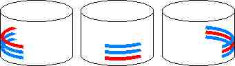
RAID 0 - Striping
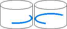
Key: = The actual data file.
In the case of striping (w/o parity) the file is split and simultaneously written to each member of the RAID0 disk array.
This is the only form of RAID that has no fault tolerance capability. A file is split in half and half is written to Drive#1 and the other half is written to Drive#2 simultaneously (in the case of striping across two drives; in a three drive stripe set the file is split into thirds, each piece is written simultaneously across the three drives, etc). This makes striping a faster read/write storage technology but if any drive in the array (it has a minimum of two drives and a maximum based on the RAID controller) fails then all data is lost.
-
RAID 1 - Mirroring
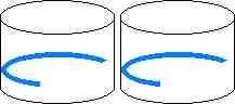
Key: = The actual data file.
In the case of mirroring or duplexing the file is simultaneously written in its entire original form to each member of the RAID1 disk array.
In RAID1, mirroring, the file (and all other file system structures) is duplicated onto the second drive. If any thing happens to either drive the system can be booted and continue operating off of the other one. This type of RAID, and all of the subsequent ones listed below is therefore fault tolerant. Mirroring causes no major performance sacrifices but is not the best in cost effectiveness since only 50% of the total storage capacity can be used. The other half of the storage capacity on the system is reserved for the mirror. In duplexing each drive is attached to an independent controller. In this case even a controller failure will not bring down the system.
-
RAID 2 - Striping w/Bit Level ECC
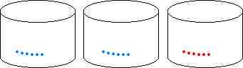
Key: = The actual data file. = the parity information.
In the case of striping w/bit level ECC the file is split one bit at a time. The first data bit will end up on Drive#1 (far left), the second data bit will end up on Drive#2 (middle), and a parity bit calculated from these two data bits will be stored on Drive#3. (far right)
This form of RAID was developed to defeat random single bit flaws that would on rare occasion occur with early IDE and SCSI hard drives. In RAID2, the file is split bit by bit. The first bit is cached in a buffer for Drive#1, the second bit goes to a buffer intended for Drive#2 and a parity bit calculated from those preceding two bits is cached to go to Drive#3. When 512 bytes (at least) have accumulated in the buffers they are written out to the drives. If any single bit read/write error occurs the system can correct it with the parity calculation and continue to function without interruption. In any one of the drives fails all files can be corrected on-the-fly from the parity calculations. If the parity Drive (#3) is the one that fails, operations continue at full speed. if either of the other drives fails, operations will slow down dramatically because each disk access must undergo a parity calculation in order to actually read the file. RAID2 was rendered effectively deprecated once drives began performing bit level ECC onboard and therefore became capable of surviving single random bit errors on their own and at a much faster speed than the RAID2. RAID2 bogs down in performance because of the necessity of splitting the bytes bit by bit and then performing a parity bit calculation for every two bits. This ends up being 4 parity calculations per byte. Subsequent RAIDs take advantage of the full width of the processor's registers and can perform the same level of ECC with far fewer calculations.
RAID3, Striping with Parity, is exactly the same as RAID2 except that instead of spliting the file bit by bit, the file is split byte by byte. The first byte goes to the cache for Drive#1, the next byte into the cache of Drive#2, and a parity byte is calculated from the previous two bytes and is placed in the cache for Drive#3. When the caches reach at least 512 bytes, they are written out to the disks. RAID3 only requires one parity calculation per two bytes and is therefore 8 times more efficient than RAID2 concerning parity calculations. Performance is therefore better under all conditions although it still suffers if either Drive#1 or Drive#2 fails. It should be noted that it appears that Adaptec is defining RAID3 very much like the definition of RAID4 below).
-
RAID 4 - Block Striping w/Parity
Key: = The actual data file. = the parity information.
In the case of block striping w/parity the file is split into blocks. The first data block will end up on Drive#1 (far left), the second data block will end up on Drive#2 (middle), and a parity block calculated from these two data blocks will be stored on Drive#3. (far right)
RAID4 functions exactly like RAIDs 2 and 3 except that it splits the file into blocks instead of bits or bytes. A RAID4 might take the file and split it into a block of 512 bytes which it places into the cache for Drive#1, the next block of 512 bytes is placed into the cache for Drive#2, and a 512 byte block of parity values is calculated from the other two blocks and placed into the cache of Drive#3, these are then written out to the disks. Block striping with parity is even faster than RAID2 or RAID3 since it can take full advantage of 32-bit program code and CPU registers. It still suffers during the failure of Drive#1 or Drive#2.
-
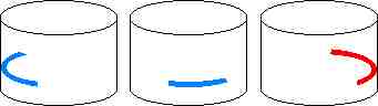
RAID 5 - Block Striping w/Distributed Parity
Key: = The actual data file. = the parity information.
In the case of block striping w/distributed parity the file is split into blocks. The first data block will end up on one of the drives, the second data block will end up on another, and a parity block calculated from these two data blocks will be stored on the remaining one.
In RAID5, the distribution of parity blocks is evened out over time. The first file gets data blocks placed on Drive#1 and Drive#2 and parity blocks on Drive#3. The next file gets data blocks stored on Drive#2 and Drive#3 and parity blocks stored on Drive#1, the third file gets data blocks stored on Drive#1 and Drive#3 and parity blocks stored on Drive#2. This process continues in this fashion so that at any moment each drive only holds 1/3 of all parity information and 2/3 real file data blocks. When a drive fails like the preceding RAIDs the system can continue to function but performance does not suffer nearly as much and performance degradation is equal regardless of which drive fails. RAID5 is the current RAID storage standard for cost effectiveness, performance and fault tolerance capabilities.
-
RAID 6 - Block Striping w/Double Distributed Parity
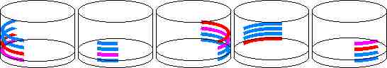
Key: = The actual data file. = the "P" parity block. = the "Q" parity block.
In the case of block striping w/double distributed parity the file is split into at least three blocks. The first data block will end up on one of the drives, the second data block will end up on another, the third on yet another and two different parity blocks called the "P" and "Q" parity blocks are calculated from these three data blocks will be stored on the remaining two drives.
RAID6 is a recent form of RAID defined in the "highest authority" of SCSI technology; the book called "The Book of SCSI". In RAID6 the minimum number of drives is 4. In this example 5 drives are used. Each file is broken in this case into three data blocks, then two separate parity blocks are constructed. Now Drive#1 gets a data block, Drive#2 gets a data block, Drive#3 gets a data block, Drive#4 gets a parity block and Drive#5 gets a parity block. The point of the two parity blocks is that the original file can be constructed from two of these and just one of the original data blocks. Notice in the above schematic that the parity blocks are being distributed evenly across the subsequent file writes like RAID5. Also notice that if any two drives are lost, the system can continue to function. RAID6 has the highest level of fault tolerance but is not much more cost effective than mirroring. The multiple parity calculations also affect performance bogging it down compared to some of the newer composite RAID schema being developed.
-
Some common "composite" RAID schema:
Type Name Definition RAID 0+1 Striping w/Mirrors The file is striped out to two drives. Each of these drives is actually a mirror set. RAID 1+0(RAID10) Mirror w/Striping: The file is written out in full duplicate to two separate drives. Each of the mirror drives is actually a stripe set. RAID 5+0(RAID50) RAID5 w/Striping: The file is broken into blocks and a parity block is calculated. Each block is written out to its respective drive. Each of these drives is in actuality a RAID0 stripe set. -
In comparing RAID 0+1 versus 1+0 consider: In RAID 0+1 the file is "striped out" to the two mirror sets. This means that BOTH sides must come back from at least one working drive. Therefore RAID 0+1 can tolerate one drive from each side of the stripe but never both. In RAID 1+0, the file is mirrored in full to each stripe set. It can lose one or both drives of either mirror set but it can never suffer a drive down in both sets at the same time.
-
RAID50 requires a minimum of six drives. It can lose one or both of any single stripe set of the three but it cannot tolerate two drives down at the same time from two different sets.
-
One can imagine implementing RAID 0+5 and so on. One company is offering a box that features "RAID 53". Some companies may reverse the authors definitions and what they call RAID 0+1 the author is calling RAID 1+0. The author is using the Adaptec definition of their "RAID 0/1" products as the definition of a generic term called "RAID 0+1". It is however, imperative to read the documentation to get a clear picture of what a particular company is refering to when they state "RAID 0+1" or RAID "1+0".
-
The key to the various definitions of RAIDs 2, 3, and 4 these days appears to be the algorithm used to access the disks. Adaptec appears to be using the author's definition of RAID4 for what they refer to as RAID3. The key issue to each of these RAIDs is their usage of a dedicated parity data drive, whereas RAID5 will distribute the file's data blocks and parity blocks evenly accross the members of the RAID5 disk array.
-
How does RAID 5 work?
Under normal circumstances parity, the student PC technician has learned, is a form of EDC or Error Detection Code, and not a form of ECC, or Error Correction Code. This is indeed true except in the case of how the RAID array controller (hardware or software) performs the calculations and reconstructions using it.
-
Here is a simple example in which the ASCII code for the letter "A" will be stored on Drive#1, the code for "B" will be stored on Drive#2 and the parity byte will be stored on Drive#3.
   ASCII Code for Capital "A" in binary:    01000001
   ASCII Code for Capital "B" in binary:    01000010 XOR
   Parity byte ("A" XOR "B"):               00000011
In the XOR logical operation if the two bits being XORed in the column are unlike (i.e. a 0 and a 1) then the XOR result is a 1. if the two bits being XORed in each column are alike (i.e. both are 0 or both are 1) then the XOR result is 0.
-
Now assume that data Drive#2 has failed. The controller can read the "A" from Drive#1 and it can read the parity byte from Drive#3. It will now use the data to reconstruct the missing data from Drive#2:
   ASCII Code for Capital "A" in binary:    01000001
   Parity byte ("A" XOR "B"):               00000011 XOR
   ASCII Code for Capital "B" in binary:    01000010
So by simply XORing the piece of data that is still intact with the XOR sum of the original data pieces then the missing piece returns! Try this with any pair of bytes and you will find that XOR does in fact exhibit this "magical" boolean logical property.
-
Boot the system to the Student CD-ROM and wipe the two drives on the secondary controller. Once complete, launch GHOST and restore the Windows 2000 Advanced Server image onto the first physical drive of the system (the one in the rack.) Be sure to set the size of the partition to be restored from the image file to 1000MB in size. When complete remove the student CD-ROM and reboot the system.
Logon as Administrator using the password "admin". Close the Configure Your Server Window and launch the Disk Management using Start > Programs > Administrative Tools > Computer Management. Maximize the screen and then single click on Disk Management.
-
This will launch the Write Signature and Upgrade Disk Wizard. Click Cancel and adjust the sizes of the Window panes so that the Disks pane of the lower right is the largest one. Notice that the two "unsigned" drives have red minus signs overlaid on their icons. Similarly to Windows NT 4.0, until the drives receive signatures, Disk Management (and the rest of the operating system) will not access them. The signature is a randomly generated 32-bit number similar to a volume serial number that is then written into the Master Boot Record. Right click on Disk 1 and click Write Signature. Be sure that both drives are checked in the resultant message box and click OK.
Now the red minus sign icons are gone and the disks have signatures in the MBR, though they still have no actual partition tables. Since we will be implementing a fault tolerant RAID Windows 2000 requires that the drives be upgraded to "Dynamic Disks." Notice that all three are currently referred to as Basic Disks. What this means functionally is that all partition information for the drive resides solely in the MBR as partition tables that can be read by all operating systems and the BIOS. When upgrading to a dynamic disk, custom information in the form of a rather large and proprietary data base of information about the partitions of all drives on the system will be written to the far back end of the addressable sectors of the drive. At that point the "Volumes" on the Dynamic disks will not be accessible by any other OS except one that can read a dynamic disk database: Windows 2000 or Windows XP/2003.
Right click on Disk 0 and select Upgrade to Dynamic Disk. Be sure that all three drives are checked in the message box then click OK. Note the three columns and the information displayed in the Disks to Upgrade message box then click Upgrade. Read the blue (i) message box carefully, then click Yes. Read the yellow /!\ message box carefully and click Yes. Read the next yellow /!\ carefully and click OK.
Upon reboot, open Disk Management again this time by Start > Settings > Control Panel > Dbl Click Administrative Tools > Dbl Click Computer Management. Single click Disk Management and resize the panes. Notice that all of the drives are now labeled Dynamic. Now right click on the C: drive NTFS Volume on Disk 0 (don't click the Disk itself, click the ocre colored volume on it) and select Add Mirror. In the Add Mirror Window click on Disk 1 and then click the Add Mirror button. Read the resultant yellow /!\ message carefully and click OK.
Notice the yellow /!\ overlay icon on Disk 1 and the Regenerating x% progress as Disk Management constructs the mirror of the system partition. When complete the /!\ overlay icon disappears and the mirrored volumes should indicate a status message of Healthy.
Minimize the Disk Management window for a moment (do NOT close it while it is building the mirror!) and open My Computer. Set the system to display hidden files and known file extensions and hidden OS files. Click Tools > Folder Options > View and make the appropriate selections in the Window then click Apply then Close. Open the C: Drive and create a new folder and name it Admin. Close My Computer and restore the Disk Management window.
Now right click on the black bordered unallocated space on Disk 2 and select Create Volume. The Create Volume Wizard starts. Click Next. In the Select Volume Type screen select Simple Volume, click Next. On the Select Disks screen leave the disk selected as Disk 2 and manually enter the size of the new volume as 1000MB. Click Next.
In the Assign Drive Letter or Path screen, select Mount this volume... and click on the Browse button. In the browse window click on the [+] next to the C: drive and then click on the folder you just created named Admin, then click OK. Now click Next.
In the Format Volume screen leave it to format as NTFS with Default cluster sizes, give the volume label = cadmin. Check the Perform Quick Format check box then click Next.
In the Completing the Create Volume Wizard you can review all of your choices, then click Finish. Remember to wait a moment for Disk Management to initiate and complete the format process then display the resulting Healthy status message. Note that this volume on Disk 2 will be the storage area for any files that get saved in the folder C:\ADMIN. The files stored in that folder will NOT be stored on Disk 0 where the rest of the C: drive is located. This is another advanced capability of the Windows 2000 dynamic disks and NTFS file system architectures and is called a volume "mount point." Notice that a partition is to a basic disk what a volume is to a dynamic disk. The major difference with dynamic disk volumes is that they are far more flexible and can involve more than one physical disk involved as the storage device for a single volume: that is another way of saying RAID although the mount point is a feature borrowed from the way Unix does things and is not a type of RAID, but the mirror created earlier was a software level RAID 1.
Once this is complete, a RAID-5 volume set will be created on the remaining space of all three drives. Right click on the 1.84GB (or whatever is available) unallocated space of Disk 0 and select Create Volume. In the Create Volume Wizard click Next.
In the Select Volume Type Screen click Raid-5 and read the description carefully, then click Next. In the Select Disks screen click Disk 1 then the Add button. Now click on Disk 2 and click the Add button again. All three disks should appear in the right side window pane. Now click Next.
In the Assign Drive Letter or Path, select Drive letter and make it the letter R. Click Next.
In the Format the Volume screen, leave it to format as NTFS, Change the volume label = data_raid5. Check the Perform Quick Format checkbox then click Next.
In the Completing the Create Volume Wizard screen you can review your choices then click Finish. Again, wait for Disk Management to format the volume.
When the creation and format of the new RAID 5 volume is complete, close Disk Management and Start > Search > File and Folders. Type in the file name *.GIF and tell it to search the C: drive. When several have been found click the Stop search button. Double click on a large one (greater than 10KB in size) and Internet Explorer will open to display the image file. Now that you know what it looks like copy it to the Admin folder. Notice that this folder now has a drive icon in the root of the C: drive. Find another image view it them copy it to the R: drive. This has been done to test the volumes later. Close the search window.
Insert a blank floppy diskette into the drive and open My Computer. Right Click on floppy drive A: and select Format. In the format window check the Quick format checkbox, then click Start. When finished close the format window. Open the root of the C: drive and copy the files NTLDR, NTDETECT.COM and BOOT.INI to the floppy.
Now open My Computer and open the root of the A: drive. Double click the file BOOT.INI. Copy the long entry under the [Operating Systems] section under itself so that there are two of these and change the second entry so that it points to the mirror physical drive by changing ...rdisk(0)... to ...rdisk(1)... Within the quotes on the same line change the text to: "Mirror on Physical Disk 1". Save and exit Notepad.exe.
Reboot the system to the bootable floppy and highlight the "Mirror on Physical Disk 1" entry and press [Enter]. The system should boot without incident to the desktop. This proves that the mirror capable diskette is working. Note that the operating system has no complaints about launching the mirror drive and with Disk 0 actually working, it is still mirroring the two as well.
Procedures
Review Questions
List and describe the 6 basic RAID schema:
What RAID schema is actually not fault tolerant? What is its purpose?
What RAID schema is considered to be the most fault tolerant? What is the minumum number of hard drives required to implement it? How many of these can fail simultaneously and the system continue to function?
Why are hardware level RAIDs considered to be better than software level RAIDs? What is a potential shortcoming of a hardware level RAID controller versus a software implemented RAID?
Which RAID schema are now considered obsolete? Explain why each one is now considered obsolete. What RAID schema has become the standard effectively rendering these predecessors obsolete? Why is it considered the standard choice?
What is the purpose of composite RAID schema? Why would someone want to implement RAID 10 rather than RAID 5? What are the minimum hard drives required for each schema? Assuming they are each 100GB in size, what is the total storage capacity of each schema?Which is more economically efficient?
Assuming that a certain type of hard drive has a 15MB/sec platter-to-buffer transfer rate, what is the minimum number of drives required to set up a stripe set that can physically operate at the maximum throughput of an ATA-6 controller? What would be the minimum number of drives needed to achieve this with fualt tolerance? What would be the best schema to use?
Describe the differences if any between disk mirroring and disk duplexing. What RAID schema are they?
List each of the basic RAID schema and the minimum number of hard drives needed to implement them:
List all of the composite RAID schema possible (avoid all obsolete basic schema) and the minimum number of hard drives needed to implement them:
List all of the basic RAID schema and the maximum number of hard drives that can be used to implement them:
List all of the composite RAID schema possible (avoid all obsolete basic schema) and the maximum number of hard drives that can be used to implement them:
Based on your answers to the previous two questions explain why RAID-10 is so popular:
RAID-5 is based on what boolean algebraic operation performed on the original data set?
Prove that the XOR sum of any two numbers can be XOR'ed with either of the originals to reveal the other by randomly choosing any two binary bytes to start:
Why is SCSI the preferred technology for implementing RAID's of any schema?
A disk imaging software is excellent for making full backups but will not support any RAID, what should be done to assure disaster recovery of the data?
Copyright©2000-2007 Brian Robinson ALL RIGHTS RESERVED